Design Control

Design Controls, 21 CFR 820.30, ISO 13485, Clause 7.3, Do It By Design, Waterfall Diagram, Verification and Validation, V&V, IOVV, Stage-Gate process, Design History File and DHF.

Design Controls Implementation

Design controls can be overwhelming, but you can learn the process using this step-by-step guide to implementing design controls.
Design and development process HD 610x1024 Design Controls ImplementationDesign Controls Implementation

You can implement design controls at any point during the development process, but the earlier you implement your design process the more useful design controls will be. The first step of implementing design controls is to create and design controls procedure. You will also need at least two of the following additional quality system procedures:

  1. Risk Management Procedure (SYS-010)
  2. Software Development and Validation (SYS-044)
  3. Usability Procedure (SYS-048)
  4. Cybersecurity Work Instruction (WI-007)

A risk management file (in accordance with ISO 14971:2019) is required for all medical devices, and usability engineering or human factors engineering (in accordance with IEC 62366-1) is required for all medical devices. The software and cybersecurity procedures listed above are only required for products with 1) software and/or firmware, and 2) wireless functionality or an access point for removable media (e.g., USB flash drive or SD card).

Step 2: Design controls training

Even though the requirement for design controls has been in place for more than 25 years, there are still far too many design teams that struggle with understanding these requirements. Medical device regulations are complex, but design controls are the most complex process in any quality system. The reason for this is that each of the seven sub-clauses represents a mini-process that is equivalent in complexity to CAPA root cause analysis. Many companies choose to create separate work instructions for each sub-clause.

Medical Device Academy’s training philosophy is to distill processes down to discrete steps that can be absorbed and implemented quickly. We use independent forms to support each step and develop training courses with practical examples, instead of writing a detailed procedure(s). The approach we teach removes complexity from your design control procedure (SYS-008). Instead, we rely upon the structure of step-by-step forms completed at each stage of the design process.

If you are interested in design control training, Rob Packard will be hosting the 3rd edition of our Design Controls Training Webinar on Friday, August 11, 2023, @ 9:30 am EDT.

Step 3: Gathering post-market surveillance data

Post-market surveillance is not currently required by the FDA in 21 CFR 820, but it is required by ISO 13485:2016 in Clause 7.3.3c) (i.e., “[Design and development inputs] shall include…applicable outputs(s) of risk management”). The FDA is expected to release the plans for the transition to ISO 13485 in FY 2024, but most companies mistakenly think that the FDA does not require consideration of post-market surveillance when they are designing new devices. This is not correct. There are three ways the FDA expects post-market surveillance to be considered when you are developing a new device:

  1. Complaints and adverse events associated with previous versions of the device and competitor devices should be identified as input to the risk management process for hazard identification.
  2. If the device incorporates software, existing vulnerabilities of the off-the-shelf software (including operating systems) should be identified as part of the cybersecurity risk assessment process.
  3. During the human factors process, you should search for known use errors associated with previous versions of the device and competitor devices; known use-related risks should also include any potential use errors identified during formative testing.

Even though the FDA does not currently require compliance with ISO 13485, the FDA does recognize ISO 14971:2019, and post-market surveillance is identified as an input to the risk management process in Clause 4.2 (see note 2), Clause 10.4, and Annex A.2.10. 

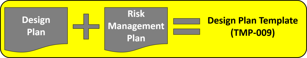
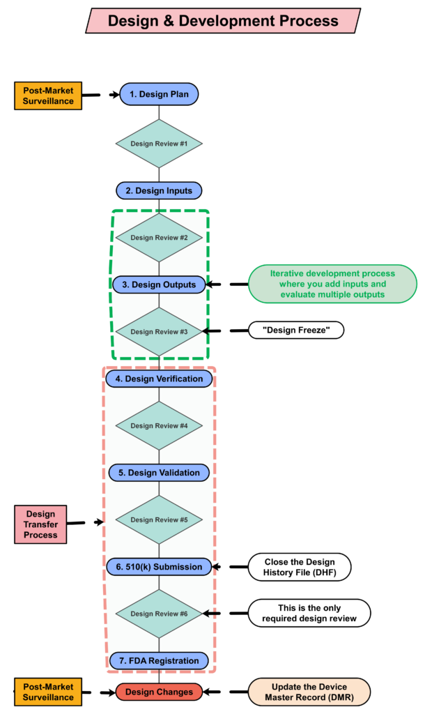
Step 4: Creating a design plan 

You are required to update your design plan as the development project progresses. Most design and development projects take a year before the company is ready to submit a 510k submission to the FDA. Therefore, don’t worry about making your first version of the plan perfect. You have a year to make lots of improvements to your design plan. At a minimum, you should be updating your design plan during each design review. One thing that is important to capture in your first version, however, is the correct regulatory pathway for your intended markets. If you aren’t sure which markets you plan to launch in, you can select one market and add more later, or you can select a few and delete one or more later. Your design plan should identify the resources needed for the development project, and you should estimate when you expect to conduct each of your design reviews.

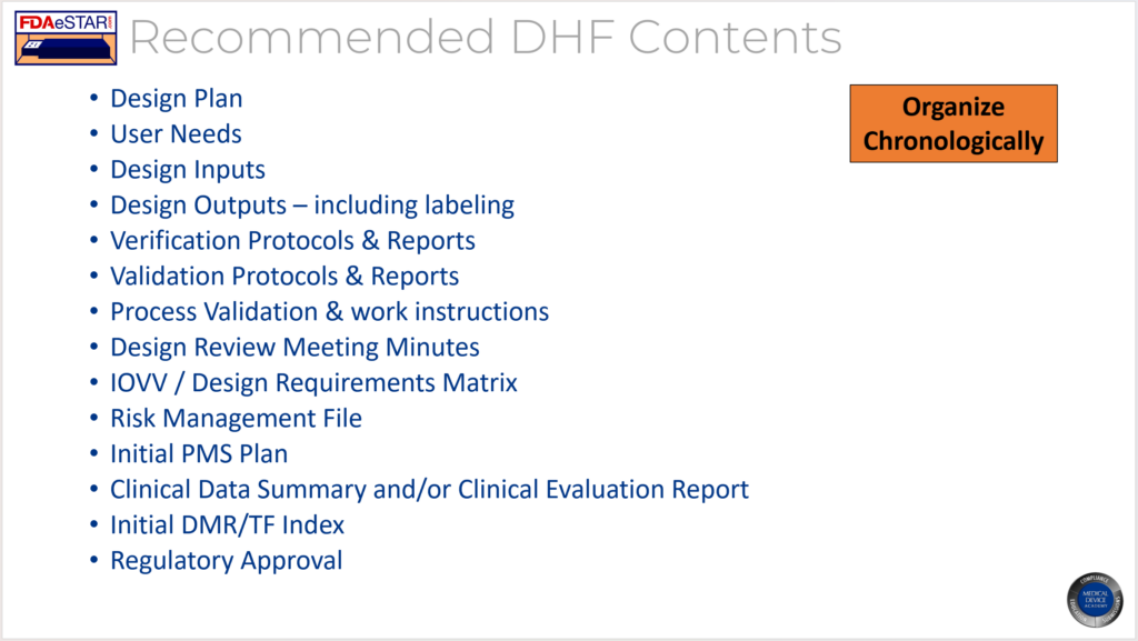
Contents of your design plan

The requirement for design plans is stated in both Clause 7.3.1 of the ISO Standards, and Section 21 CFR 820.30b of the FDA QSR. You can make your plan as detailed as you need to, but I recommend starting simple and adding detail. Your first version of a design plan should include the following tasks:

  • Identification of the regulatory pathway based on the device risk classification and applicable harmonized standards.
  • Development of a risk management plan
  • Approval of your design plan (1st design review) 
  • Initial hazard identification
  • Documentation and approval of user needs and design inputs (2nd design review) 
  • Risk control option analysis
  • Reiterative development of the product design
  • Risk analysis 
  • Documentation and approval of design outputs implementation of risk control measures (3rd design review) 
  • Design verification and verification of the effectiveness of risk control measures (4th design review)
  • Design validation and verification of the effectiveness of risk control measures that could not be verified with verification testing alone
  • Clinical evaluation and benefit/risk analysis (5th design review)
  • Development of a post-market surveillance plan with a post-market risk management plan
  • Development of a draft Device Master Record/Technical File (DMR/TF) Index
  • Regulatory approval (e.g., 510k clearance) and closure of the Design History File (DHF)
  • Commercial release (6th and final design review)
  • Review lessons learned and initiate actions to improve the design process

Step 5: Create a detailed testing plan

Your testing plan must indicate which recognized standards you plan to conform with, and any requirements that are not applicable should be identified and documented with a justification for the non-applicability. The initial version of your testing plan will be an early version of your user needs and design inputs. However, you should expect the design inputs to change several times. After you receive feedback from regulators is one time you may need to make changes to design inputs. You may also need to make changes when you fail your testing (i.e., preliminary testing, verification testing, or validation testing). If your company is following “The Lean Startup” methodology, your initial version of the design inputs will be for a minimum viable product (i.e., MVP). As you progress through your iterative development process, you will add and delete design inputs based on customer feedback and preliminary testing. Your goal should be to fail early and fail fast because you don’t want to get to your verification testing and fail. That’s why we conduct a “design freeze,” prior to starting the design verification testing and design transfer activities.

Design Timeline with 513g 1024x542 Design Controls Implementation

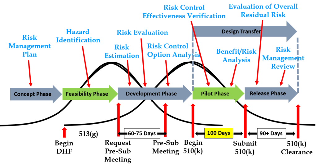
Step 6: Request a pre-submission meeting with the FDA

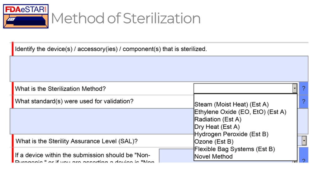
Design inputs need to be requirements verified through the use of a verification protocol. If you identify external standards for each design input, you will have an easier time completing the verification activities, because verification tests will be easier to identify. Some standards do not include testing requirements, and there are requirements that do not correspond to an external standard. For example, IEC 62366-1 is an international standard for usability engineering, but the standard does not include specific testing requirements. Therefore, manufacturers have to develop their own test protocol for validation of the usability engineering controls implemented. If your company is developing a novel sterilization process (e.g., UV sterilization), you will also need to develop your own verification testing protocols. In these cases, you should submit the draft protocols to the FDA (along with associated risk analysis documentation) to obtain feedback and agreement with your testing plan. The method for obtaining written feedback and agreement with a proposed testing plan is to submit a pre-submission meeting request to the FDA (i.e., PreSTAR).

Step 7: Iterative development is how design controls really work

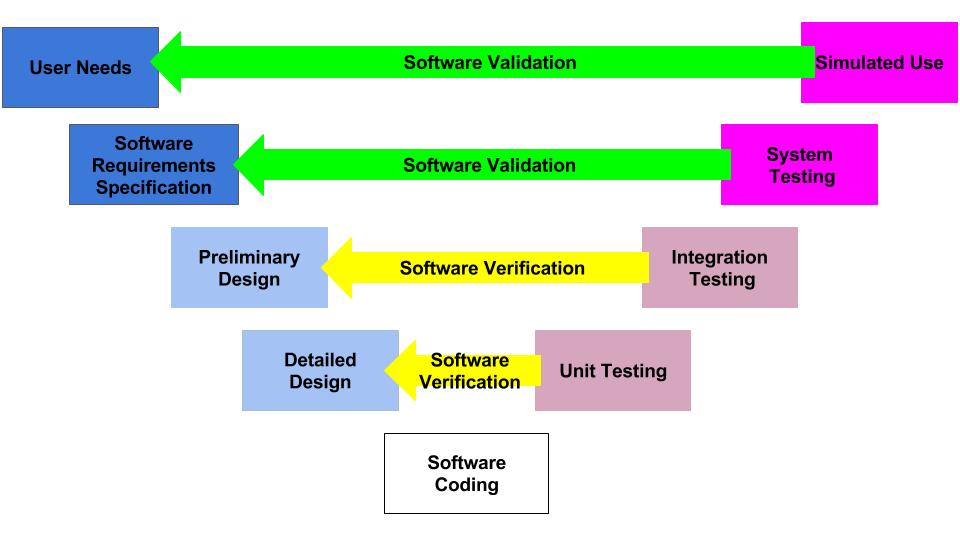
Design controls became a legal requirement in the USA in 1996 when the FDA updated the quality system regulations. At that time, the “V-diagram” was quite new and limited to software development. Therefore, the FDA requested permission from Health Canada to reprint the “Waterfall Diagram” in the design control guidance that the FDA released. Both diagrams are models. They do not represent best practices, and they do not claim to represent how the design process is done in most companies. The primary information that is being communicated by the “Waterfall Diagram” is that user needs are validated while design inputs are verified. The diagram is not intended to communicate that the design process is linear or must proceed from user needs, to design inputs, and then to design outputs. The “V-Diagram” is meant to communicate that there are multiple levels of verification and validation testing that occur, and the development process is iterative as software bugs are identified. Both models help teach design and development concepts, but neither is meant to imply legal requirements. One of the best lessons to teach design and development teams is that this is a need to develop simple tests to screen design concepts so that design concepts can fail early and fail fast–before the design is frozen. This process is called “risk control option analysis,” and it is required in clause 7.1 of ISO 14971:2019.

Step 8: “Design Freeze”

Design outputs are drawings and specifications. Ensure you keep them updated and control the changes. When you finally approve the design, this is approval of your design outputs (i.e., selection of risk control options). The final selection of design outputs or risk control measures is often conducted as a formal design review meeting. The reason for this is that the cost of design verification is significant. There is no regulatory or legal requirement for a “design freeze.” In fact, there are many examples where changes are anticipated but the team decides to proceed with the verification testing anyway. The best practice developed by the medical device industry is to conduct a “design freeze.” The design outputs are “frozen” and no further changes are permitted. The act of freezing the design is simply intended to reduce the business risk of spending money on verification testing twice because the design outputs were changed during the testing process. If a device fails testing, it will be necessary to change the design and repeat the testing, but if every person on the design team agrees that the need for changes is remote and the company should begin testing it is less likely that changes will be made after the testing begins.

Step 9: Begin the design transfer process

Design transfer is not a single event in time. Transfer begins with the release of your first drawing or specification to purchasing and ends with the commercial release of the product. The most common example of a design transfer activity is the approval of prototype drawings as a final released drawing. This is common for molded parts. Several iterations of the plastic part might be evaluated using 3D printed parts and machined parts, but in order to consistently make the component for the target cost an injection mold is typically needed. The cost of the mold may be $40-100K, but it is difficult to change the design once the mold is built. The lead time for injection molds is often 10-14 weeks. Therefore, a design team may begin the design transfer process for molded parts prior to conducting a design freeze. Another component that may be released earlier as a final design is a printed circuit board (PCB). Electronic components such as resistors, capacitors, and integrated circuits (ICs) may be available off-the-shelf, but the raw PCB has a longer lead time and is customized for your device.

Step 10: Verification of Design Controls

Design verification testing requires pre-approved protocols and pre-defined acceptance criteria. Whenever possible, design verification protocols should be standardized instead of being project-specific. Information regarding traceability to the calibrated equipment identification and test methods should be included as a variable that is entered manually into a blank space when the protocol is executed. The philosophy behind this approach is to create a protocol once and repeat it forever. This results in a verification process that is consistent and predictable, but it also eliminates the need for review and approval of the protocol for each new project. Standardized protocols do not need to specify a vendor or dates for the testing, but you might consider documenting the vendor(s) and duration of the testing in your design inputs to help with project management and planning. You might also want to use a standardized template for the format and content of your protocol and report. The FDA provides a guidance document specifically for the report format and content for non-clinical performance testing.

Step 11: Validation of Design Controls

Design validation is required to demonstrate that the device meets the user’s and patient’s needs. User needs are typically the indications for use–including safety and performance requirements. Design validation should be more than bench testing. Ensure that animal models, simulated anatomical models, finite element analysis, and human clinical studies are considered. One purpose of design validation is to demonstrate performance for the indications for use, but validating that risk controls implemented are effective at preventing use-related risks is also important. Therefore, human factors summative validation testing is one type of design validation. Human factors testing will typically involve simulated use with the final version of the device and intended users. Validation testing usually requires side-by-side non-clinical performance testing with a predicate device for a 510k submission, while CE Marking submissions typically require human clinical data to demonstrate safety and performance.

Step 12: FDA 510k Submission

FDA pre-market notification, or 510k submission, is the most common type of regulatory approval required for medical devices in the USA. FDA submissions are usually possible to submit earlier than other countries, because the FDA does not require quality system certification or summary technical documents, and performance testing data is usually non-clinical benchtop testing. FDA 510k submissions also do not require submission of process validation for manufacturing. Therefore, most verification and validation is conducted on “production equivalents” that were made in small volume before the commercial manufacturing process is validated. The quality system and manufacturing process validation may be completed during the FDA 510k review.

Step 13: The Final Design Review 

Design reviews should have defined deliverables. We recommend designing a form for documenting the design review, which identifies the deliverables for each design review. The form should also define the minimum required attendees by function. Other design review attendees should be identified as optional—rather than required reviewers and approvers. If your design review process requires too many people, this will have a long-term impact upon review and approval of design changes.

The only required design review is a final design review to approve the commercial release of your product. Do not keep the DHF open after commercial release. All changes after that point should be under production controls, and changes should be documented in the (DMR)/Technical File (TF). If device modifications require a new 510k submission, then you should create a new design project and DHF for the device modification. The new DHF might have no changes to the user needs and design inputs, but you might have minor changes (e.g., a change in the sterilization method requires testing to revised design inputs).

Step 14: FDA Registration

Within 30 days of initial product distribution in the USA, you are required to register your establishment with the FDA. Registration must be renewed annually between October 1 and December 31, and registration is required for each facility. If your company is located outside the USA, you will need an initial importer that is registered and you will need to register before you can ship the product to the USA. Non-US companies must also designate a US Agent that resides in the USA. At the time of FDA registration, your company is expected to be compliant with all regulations for the quality system, UDI, medical device reporting, and corrections/removals.

Step 15: Post-market surveillance is the design control input for the next design project

One of the required outputs of your final design review is your DMR Index. The DMR Index should perform a dual function of also meeting technical documentation requirements for other countries, such as Canada and Europe. A Technical File Index, however, includes additional documents that are not required in the USA. One of those documents is your post-market surveillance plan and the results of post-market surveillance. That post-market surveillance is an input to your design process for the next generation of products. Any use errors, software bugs, or suggestions for new functionality should be documented as post-market surveillance and considered as potential inputs to the design process for future design projects.

Step 16: Monitoring your design controls process

Audit your design controls process to identify opportunities for improvement and preventive actions. Audits should include a review of the design process metrics, and you may consider establishing quality objectives for the improvement of the design process. This last step, and the standardization of design verification protocols in step five (5), are discussed in further detail in another blog by Medical Device Academy.

Design Controls Implementation Read More »

Iterative design is real, waterfalls are illusions

The Waterfall Diagram was copied by the FDA from Health Canada and ISO 9001:1994, but everyone actually uses an iterative design process.

Iterative Design – What is it?

The FDA first mandated that medical device manufacturers implement design controls in 1996. Unfortunately, in 1996 the design process was described as a linear process. In reality, the development of almost every product, especially medical devices, involves an iterative design process. The V-diagram from IEC 62304 is closer to the real design control process, but even that process is oversimplified.

Software Validation and Verification 1 Iterative design is real, waterfalls are illusions

What is the design control process?

The design control process is the collection of methods used by a team of people and companies to ensure that a new medical device will meet the requirements of customers, regulators, recognized standards, and stakeholders. With so many required inputs, it is highly unlikely that a new medical device could ever be developed in a linear process. The design control process must also integrate risk management and human factors disciplines. ISO 14971:2019, the international risk management standard, requires conducting optional control analysis. Option control analysis requires evaluating multiple risk control options and selecting the best combination of risk controls for implementation. The human factors process involves formative testing where you evaluate different solutions to user interfaces, directions for use, and training. This always requires multiple revisions before the user specifications are ready to be validated in summative usability testing. Process success is verified by conducting verification and validation testing. The process ends when the team agrees that all design transfer activities are completed, and your regulatory approval is received.

waterfall fda Iterative design is real, waterfalls are illusions

Where did design controls come from?

The diagram above is called the “Application of Design Controls to Waterfall Design Process.” The FDA introduced this diagram in 1997 in the design controls guidance document. However, the original source of the diagram was Health Canada.

This diagram is one of the first slides I use for every design control course that I teach because the diagram visually displays the design control process. The design controls process, defined by Health Canada and the US FDA, is equivalent to the design and development section found in ISO 13485 and ISO 9001 (i.e., – Clause 7.3). Seven sub-clauses comprise the requirements of these ISO Standards:

  • 7.3.1 – Design Planning
  • 7.3.2 – Design Inputs
  • 7.3.3 – Design Outputs
  • 7.3.4 – Design Reviews
  • 7.3.5 – Design Verification
  • 7.3.6 – Design Validation
  • 7.3.7 – Design Changes

In addition to the seven sub-clauses found in these ISO Standards, the FDA Quality System Regulation (QSR) also includes additional requirements in the following sub-sections of 21 CFR 820.30: a) general, h) design transfer, and J) Design History File (DHF). If you need a procedure(s) to comply with design controls, we offer two procedures:

  1. Design Controls (SYS-008)
  2. Change Control (SYS-006)

The change control process was separated from the design controls process because it is specific to changes that occur after a device is released to the market. We also have a training on Change Control.

Free Download – Overview of the Design & Development Process

What are the phases of the Design Control Process?

Normally, we finish the design control process by launching your device in the USA because this is when you should close your Design History File (DHF). However, if you are going to expand to different markets, there is a specific order we recommend. We recommend the US market first because no quality system certification is required, and the FDA 510(k) process is easier than the CE Marking process due to the implementation of the MDR and the IVDR. The Canadian market is the second market we recommend because the Canadian Device License Application process for Health Canada is even easier than the 510(k) process for Class II devices. The Canadian market is not recommended as the first country to launch because Health Canada requires MDSAP certification for your quality system, and the Canadian market is 10% of the US market size. The European market should probably be your last market because of the high cost and long timeline for obtaining CE Marking. Each of the phases of design and development is outlined in the first column of our free download, “Overview of Regulatory Process, Medical Device Development & Quality System Planning for Start-ups.”

Which regulatory filings are required during each phase of design and development?

The second column of our free download lists the regulatory filings required by the FDA for each phase. Generally, we see companies waiting too long to have their first pre-submission meeting with the FDA or skipping the pre-submission meeting altogether. This is a strategic mistake. Pre-submission meetings are free to submit to the FDA, and the purpose of the meeting is to answer your questions. Even if you are 100% confident of the regulatory pathway, you know precisely which predicate you plan to use, and you know which verification tests you need to complete, you still have intelligent questions that you can ask the FDA. Critical questions fall into three categories: 1) selection of your test articles, 2) sample size justification, and 3) acceptance criteria. Even if you don’t have a complete testing protocol prepared for the FDA to review, you can propose a rationale for your test article (e.g., the smallest size in your product family). You can also provide a paragraph explaining the statistical justification for your sample size. You might also present a paragraph explaining the data analysis method you plan to use.

The following example illustrates how discussing the details of your testing plan with the FDA can help you avoid requests for additional information and retesting. Many of the surgical mask companies that submitted devices during the Covid-19 pandemic found that the FDA had changed the sample size requirements, and they were now requiring three non-consecutive lots with a 4% AQL sample size calculation. If the company made a lot of 50,000 masks, they would be forced to sample a large number of masks, while a lot size of 250 masks allowed the company to sample the minimum sample size of 32 masks.

If the regulatory pathway for your device is unclear, you might start with the submission of a 513(g) submission during the first phase of design and development. After you have written confirmation of the correct regulatory pathway from the FDA, you can submit a pre-submission meeting request to the FDA. If the pathway for your device is a De Novo Classification Request, you might have a preliminary pre-submission meeting to get an agreement with the FDA regarding which recognized standards should be applied as Special Controls for your device. While waiting 70+ days for your pre-submission meeting with the FDA, you can obtain quotes from testing labs and prepare draft testing protocols. After the presubmission meeting, you can submit a pre-submission supplement that includes detailed testing protocols–including your rationale for the selection of test articles, sample size justification, and the acceptance criteria.

What quality assurance documentation is required during each phase?

In addition to testing reports for your verification and validation testing, you will find many other supporting documents you also need to prepare. We refer to these supporting documents generically as “quality assurance documentation” because the documents verify that you meet specific customer and regulatory requirements. However, the documents should be prepared by the person or people responsible for that portion of your design project. For example, every device will need a user manual and draft labeling. Even though you will need someone from quality to complete a regulatory checklist to ensure that all of the required symbols and general label content are included, you will also need an electrical engineer to prepare sections of the manual with EMC labeling requirements from the FDA’s EMC guidance document. In your submission’s non-clinical performance testing section, you must include human factors documentation in addition to your summative usability testing report. For example, you will need a use specification, results of your systematic search of adverse events for use errors, a task analysis, and a Use-Related Risk Analysis (URRA). Software and cybersecurity documentation includes several documents beyond the testing reports as well.

Which procedures do you need to implement during each development phase?

The last column of our free download lists the procedures we recommend implementing during each phase of the design process. In Canada and Europe, you must complete the implementation of your entire quality system before submitting a Canadian License Application or CE Marking application. In the USA, however, you can finish implementing your quality system during the FDA review of your 510k submission or even after 510k clearance is received. The quality system requirement is that your quality system is fully implemented when you register your establishment with the FDA and begin distribution.

Iterative design is real, waterfalls are illusions Read More »

Artificial Intelligence and Machine Learning Medical Devices

The FDA released a new draft guidance document about artificial intelligence and machine learning (AI/ML) functions in medical devices.

What is a predetermined change control plan for artificial intelligence (AI) software?

The new FDA guidance is specific to predetermined change control plans for marketing submissions. The guidance was released on March 30, 2023, but the document is dated April 3, 2023. The draft guidance applies to artificial intelligence (AI) or Machine Learning-Enabled Device Software Functions (ML-DSF), including modifications automatically implemented by the software and modifications to the models implemented manually.

New Artificial Intelligence PCCP Guidance Document 1024x857 Artificial Intelligence and Machine Learning Medical Devices

A PCCP must be authorized through 510k, De Novo, or PMA pathways, as appropriate. The purpose of including a PCCP in a marketing submission is to seek premarket authorization for these intended device modifications without necessitating additional marketing submissions for each change described in the PCCP.

How do you determine if a 510k is required for a device modification, and how would a PCCP affect this?

Currently, there are three guidance documents relating to the evaluation of changes and determination if a new premarket submission is required:

These guidance documents will still be the first steps in evaluating changes. Only changes specific to artificial intelligence (AI) or ML-DSF that would result in a new pre-market submission could be subject to a PCCP.

Examples of Employing AI/ML-DSF PCCPs

  • Retraining a model with more data to improve device performance while maintaining or increasing sensitivity. If this type of change is pre-approved in the PCCP, the labeling can be updated to reflect the improved performance once the change has been implemented. 
  • Extending the scope of compatible hardware with a device system. For example, if the algorithm was initially trained using one specific camera, ultrasound, defined parameter, etc., then a PCCP could add additional cameras/ultrasounds/modified parameters. 
  • Retraining a model to optimize site-specific performance for a specific subset of patients with a particular condition for whom sufficient data was unavailable. The PCCP could expand the indications once such data were available.

What is the difference between a locked vs. adaptive algorithm?

A locked algorithm is a software function involving human input, action, review, and/or decision-making before implementation. Once the algorithm is designed and implemented, it cannot be changed without modifying the source code.

Locked algorithms contrast with adaptive/automatic algorithms, where the software will implement changes without human intervention. The adaptive/automatic algorithms are designed to adjust according to changing input conditions. The adaptive/automatic algorithm is designed to recognize patterns in the input data and adjust its processing accordingly.

Typically locked algorithms apply to fixed functions such as a decision tree, static look-up table, or complex classifier. For AI/ML-DSF, manually implemented algorithms may involve training the algorithm on a new dataset or serving a new function. Once the training is complete, the algorithm will be implemented into the software. Adaptive algorithms are programmed such that their behavior changes over time as it is run based on the information it processes.

As it relates to a PCCP, the detailed description of the intended modifications needs to specify which algorithm type is being modified.

What is included in a PCCP for artificial intelligence (AI) software?

A PCCP should consist of:

  • Detailed Description of Intended Modifications
  • Modification Protocol describing the verification and validation activities, including pre-defined acceptance criteria
  • Impact Assessment identifying the benefits and risks introduced by the changes

The detailed description of the intended modifications should list each proposed device modification and the rationale for each change. If changes require labeling modifications, that should also be described. It should also be clearly stated whether or not the proposed change is intended to be implemented automatically or manually. The description should describe whether the change will be implemented globally across all devices on the market or locally, specific to different devices based on the unique characteristics of the device’s patient or clinical site.

The types of modifications that are appropriate for a PCCP include modifications related to quantitative measurements of ML-DSF performance specifications, changes related to device inputs, and limited modifications relating to the device’s use and performance. The draft guidance provides some examples of each of those modification types. 

The content of the modification protocol section requires a description of planned data management practices relating to the reference standard and annotation process, a description of re-training practices and processing steps, performance evaluation methods and acceptance criteria, and internal procedures for implementing updates. 

The impact assessment is the documentation of the evaluation of the benefits and risks of implementing the PCCP for the software. Any controls or mitigations of the risks should be described in this section. 

Appendix A of the draft guidance includes example elements of modification protocol components for ML-DSFs. Appendix B includes examples of ML-DSF scenarios employing PCCPs.

If, at some point, the manufacturer wants to make changes to the content of the PCCP relating to either the modifications described or the methods used to validate those changes, that generally would require a new marketing submission for the device. 

Utilizing a PCCP in your QMS Change Control System

When evaluating and implementing changes, the manufacturer shall do so in accordance with their Quality Management System change control processes. This should require a review of planned modifications against the FDA guidance documents for evaluating changes and the PCCP. For the change to be acceptable under the PCCP, it must be specified in the Description of Modifications and implemented in conformance with the methods and specifications described in the Modification Protocol. A new premarket submission is required if it does not meet those requirements.

Artificial Intelligence and Machine Learning Medical Devices Read More »

NSE letter: A CAPA plan for your 510k process

Cry, complain, call the reviewer…you might feel a little better, but you received an NSE letter, and tomorrow you still can’t sell your device.

NSE Letter NSE letter: A CAPA plan for your 510k process

Instead, try approaching an NSE letter like a CAPA investigation. What is the issue? The FDA determined that your device is not substantially equivalent to the predicate you selected. What is the root cause? There are four (4) possible root causes.

NSE Letter Cause #1: You failed to verify that the predicate is a legally marketed device.

If your predicate device is not legally marketed, you need to select a new predicate and resubmit. However, it is doubtful that your device would pass the refusal to accept the (RTA) screening process if the predicate was not legally marketed. If your predicate was not registered and listed with the FDA (check using this link), then you should have submitted a pre-sub request to determine if the agency has any problem with using the device you chose as a predicate. This is an essential question if the manufacturer is no longer in business, and the product is no longer for sale.

NSE Letter Cause #2: You failed to evaluate the substantial equivalence of your device’s intended use with the predicate.

The intended use of your predicate device is documented for every potential predicate since February 1992 on FDA Form 3881–which you can download along with the 510k clearance letter for the predicate. There is also an intended use documented for every device category in the applicable regulation for that device. This intended use is more generic than FDA Form 3881, but both are applicable. The FDA Form 3881 you submit for your device must be equivalent. I recommend a point-by-point comparison with regard to the following elements: 1) OTC vs. prescription use, 2) user, 3) patient population, 4) illness or medical condition, 5) duration of use, 6) environment of use and 7) target part of the body. Any difference can raise new issues of risk and may result in an NSE decision. However, the FDA typically will work with the company to modify the wording of FDA Form 3881 to ensure the intended use is equivalent or to make sure you provide clinical evidence to address the differences. In my pre-submission requests, I include a comparison document for the intended use to ensure that the FDA is aware of any differences in the intended use.

Cause #3: You failed to convince the FDA that technological differences do not raise different questions of safety and effectiveness.

Unless your device is identical in every way to the predicate device, you will have to persuade the FDA that differences do not raise questions of safety and effectiveness. At the beginning of the 510(k) process, it is helpful to document technological differences systematically. Specifically, this should include: 1) materials, 2) design, 3) energy source, and 4) other features. For each difference, you must justify why the difference does not raise different issues, or you must provide data to prove it. It is also possible that you were not aware of questions of safety and performance raised by technological differences. To avoid this problem, you can submit a detailed device description and draft labeling to the FDA in a pre-sub meeting request. If you ask questions about differences in a pre-sub meeting, you can avoid an NSE letter.

Cause #4: You failed to provide data demonstrating equivalence.

For each difference, you should determine an objective method for demonstrating that the difference is equivalent in safety and performance to the predicate. Your test method can be proposed to the FDA in a pre-sub request before testing. The FDA sees more than 3,000 companies propose testing methods to demonstrate equivalence each year. They have more experience than you do. Ask them in a pre-sub before you test anything. There may be a better test method, or you might need to adjust your test method. Sometimes results are unclear, but there might be another test you can perform to demonstrate equivalence, and then you can resubmit your 510k. Possibly you were unaware of the need to perform a test, and you were unable to complete a test within the 180 days the FDA allowed for submitting additional information. The good news is you now have all the time you need.

What is similar between all four causes of the NSE letter?

In all four root causes identified above, you could benefit greatly from the pre-sub meeting. Now you have an NSE letter, and you know which of the four reasons why your submission did not result in 510(k) clearance. However, the correction to your NSE letter may not be clear. Therefore, you should consider requesting a pre-sub meeting as quickly as you can. Most companies choose not to submit a pre-sub meeting request because they don’t want to wait 60-75 days. However, sometimes pre-sub meetings are scheduled sooner. In addition, 60-75 days is not as costly as receiving a second NSE letter.

Prevent a future NSE letter by requesting a pre-sub meeting

Regardless of your corrections for the current NSE letter, you should prevent future occurrences by planning to submit a pre-sub meeting request for every submission. I try to help clients gather all the information they need without a pre-sub meeting, but each new 510k reminds me why a pre-sub meeting is so valuable. You always learn something that helps you with the preparation of your 510k.

Help with Pre-sub meeting requests

The FDA published a guidance document for pre-sub meeting requests. If you need additional help, there is a webinar on this topic.

NSE letter: A CAPA plan for your 510k process Read More »

Design change control – best practices in managing changes?

This article describes best practices in managing your design change control process, including a list of the ten most common mistakes.

Tire Change Image for Change Control Blog Design change control   best practices in managing changes?

During every visit by FDA inspectors, and CE Marking auditors, the changes you have made will be reviewed. The focus by inspectors and auditors is: 1) to verify that your design verification and validation was adequate for the changes, and 2) to verify that necessary regulatory approval of the changes was obtained. Due to this scrutiny, your design change control process is one of the most important processes to manage well.

Ten most common mistakes in managing design change control

  1. Failure to carefully update drawings and specifications. Often these errors are typos, but it is essential to perform a thorough review of all your drawing dimensions, tolerances, notes, etc.
  2. Failure to update procedures and work instructions, especially inspection instructions. As a quality system becomes more mature, it becomes harder to identify all the places where a reference is found. If you have a 100% electronic quality system, with the ability to include cross-references, finding the related documents is easier. MasterControl uses “info cards.” It is possible to do this in any system by adding tags to your master document list. The “tags” can be standards, regulations, other procedures, and forms.
  3. Failure to validate inspection methods. Often a new inspection tool or method may appear to be better, but it is important to re-validate inspection methods whether you are changing: 1) design, 2) inspection tools, or 3) inspection methods. A Gauge R&R study is an example of one method for the validation of inspection methods.
  4. Failure to re-verify and re-validate your design. In general, whenever you make a design or process change, you need to repeat your verification and validation that was initially performed. You may be able to abbreviate the verification and validation testing. Still, if you cannot provide a justification for the abbreviated method, then you should use the same method and the same acceptance criteria. This presents an enormous burden for any device that required a clinical study to demonstrate safety and effectiveness. This is also why it is so expensive to implement changes in CE Marking for Class III devices, and FDA approved Class III PMA devices. In both cases, there is typically a large supplement required for regulatory approval.
  5. Failure to update your risk management documentation and post-market surveillance plans. Risk management files and post-market surveillance plans are meant to be “living documents.” Therefore, whenever you make changes, even minor ones, you should document your evaluation of the need to update the risk management file or your PMS plan. If the changes planned are related to a CAPA or recall, it is critical to verify the effectiveness of the changes made. This verification is both verification of the design change and the effectiveness of your risk controls. It will also be critical to document the change in the PMS plan by identifying potential confusion and use errors associated with your change.
  6. Failure to change UDI. Most companies created their change control procedure in the early stages of their quality system, and very few revisions and updates are made to the change control procedure and associated forms. Your UDI process and procedure are probably much more recent, and many companies forget to add UDI requirements to their change control process. It is important to update your device identifier, not only for regulatory compliance but also as a tool to help your company better track which quality issues are related to the previous version of your device and which quality issues are limited to the new version.
  7. Since the EU MDR requires that DI portion of your UDI is included in your Declaration of Conformity, this is another document to make sure you update when you make a design change. I recommend identifying the date (or lot) of first CE Marking and last CE Marking for your previous version in an updated Declaration of Conformity. Then you will also need the date of first CE Marking for the new version of your product. This can create a very long and complicated declaration. Still, it is important to control these transitions in anticipation of potential complaint investigations during the period of time when both versions are in distribution/use.
  8. Failure to update your technical file and device master record (DMR). Every time you change a drawing, specification, tolerance, testing method, etc. you need to update your technical documentation and DMR. This is why using a Technical File Index, and DMR Index are considered best practices. These tools just list all the related controlled documents and the current revision. The best indices will also identify how revisions were controlled (e.g., change notification or design change order). You might even identify which CE Certificate or 510(k) clearance is associated with each item in the index. This is especially helpful when you have multiple accessories involved. FDA inspectors will verify that you updated your DMR, and they will review the MDR for design changes that were not adequately validated. Your Notified Body will also review changes made to your Technical File to make sure you have notified them of changes or obtained prior approval to commercial release.
  9. Failure to document your rationale for no new regulatory approval. Whenever you make a change, you need to document your rationale for whether a new regulatory submission is required. You should have a systematic method that is documented. The FDA has published two guidance documents with decision trees to assist with this decision for 510(k) cleared products: 1) Deciding When to Submit a 510(k) for a Change to an Existing Device, and 2) Deciding When to Submit a 510(k) for a Software Change to an Existing Device. For CE Marking and Canadian Licensing, there are guidance documents on determining when a submission is required for significant changes. Regardless of your decision, you need to document the decision, and the form you use to document this decision should be a controlled form within your change control process.
  10. Failure to notify suppliers of your changes. Whenever you make a change, it is critical to notify your suppliers of the change. However, you also need to determine if the change may impact any open purchase orders. Will you need to rework or scrap any work in progress? Will you need to coordinate the use of components so that all components are used up before the change? There may even be obsolete inventory that you need to disposition as “use-as-is” or “rework.”

Create controlled templates for verification and validation testing

For every verification and validation test that you perform, you should have some kind of documented testing plan or formal protocol. Plans are more appropriate when the testing will be outsourced to a lab that has their testing protocols. If you are performing the testing in-house, you should have a formal protocol that references any internal testing work instructions that may be relevant and any testing standards that apply. The protocols should also be designed for “fill-in-the-blank” use to facilitate reuse of the protocol for multiple devices. Protocols should also identify the following required elements: 1) facilities needed for testing, 2) calibrated devices needed for measurement, 3) any controlled documents or standard referenced in the protocol, 4) sample requirements, 5) acceptance criteria, and 6) statistical rationale for sample sizes. The FDA also released a guidance document defining the format and content for testing reports. Whenever a standard is revised, it will also be important to assess the impact on current regulatory approval. CE Marked products will need to be retested to the new standards, or at least a scientific justification must be provided. By maintaining these plans and protocols as controlled documents, you will be able to execute testing plans and protocols much more quickly and consistently. You may also want to consider maintaining an appendix for testing plans that identifies any vendors and contacts for obtaining quotations for new testing.

Organizing design change control approval forms

One of the biggest mistakes people make is to try and streamline questions down to checkboxes or yes/no questions. For example, don’t ask the question, “Is 510(k) clearance required for this change?” Instead, require the person always to fill out a form to document the decision for whether a 510(k) is required or not–which should also be a controlled form. Don’t ask the person if there is an inventory that is affected by the change. Instead, ask the person to identify how many units are at each stage of the process (i.e., pending purchase orders, inspection quarantine, and finished good inventory). Then ask the person to identify the disposition for the product at each stage. This would typically be documented with a nonconforming material record (i.e., NCMR). You should also define which roles and responsibilities complete each part of your form unless you have a small company where key individuals are responsible for multiple roles.

Who should approve design changes?

There is no specific requirement for who must review and approve changes, but each document that is revised and updated will need to be reviewed and approved by the same functions that approved the previous version. Therefore, it would make sense that the same functions that reviewed and approved the design in a final design review should also be involved in the review and approval of a design change for the same device. There is no requirement for an independent reviewer for design change review and approval. Still, I have observed so many mistakes, and I think an independent reviewer and approver are extremely valuable for design changes.

What if you are facing a deadline

There is always pressure from peers and superiors to release design changes to the market as soon as possible. In theory, everything new is better, but this is often untrue. Forcing everyone to follow your change control process is intended to prevent the release of a product that is not ready for release. Therefore, you should fill out as much of your design change approval form at the beginning of a design change as possible. This will help everyone identify the documentation updates at the beginning. All the documentation and testing that is required should be planned, target dates for completion of each update should be documented, and the person responsible for each updated document should be identified. By documenting your plan and maintaining that plan, everyone will know what needs to be completed before a modified device can be released. By controlling the changes in this way, it becomes the responsibility of the whole team to make sure the responsible person and on-time complete each document. If you adopt this strategy, more device changes will be released on-time. You will also find that fewer mistakes will be made, and the team will share the burden of meeting launch deadlines.

Are “full” design controls required?

For minor design changes, you don’t want to apply “full” design controls and create a new design history file (DHF). However, you may want to create a shorter version of a design plan to document what level of control is required and how the project will be managed. This could be as short as a page, but it is likely to be several pages. The following is a list providing examples of things you might document in the abbreviated plan for control of design changes:

  1. Previous regulatory approvals [e.g., 510(k) number]
  2. Applicable Technical File or DMR Index that will be updated
  3. Any new risks identified
  4. Any new applicable standards
  5. Approved Design Inputs (indicate if changes are needed)
  6. Design Outputs that need to be updated (consider highlighting in your DMR index)
  7. Changes to your supply chain (e.g., process changes, supplier changes, supplier quality agreements, and process changes)
  8. Process validation and Revalidation required
  9. Labeling and UDI changes
  10. Obsolescence of inventory and reverse/forward compatibility of components
  11. Impact on service procedures and/or providers
  12. Changes and changeover of internal calibrated tooling and testing stations

What if you are making a design change before a product is commercialized?

The quality system requirement for control of design changes also applies to changes made before the release of a product. During the design process, changes made before “design freeze” will be frequent. For these changes, you want to make the process as simple as possible. Once you begin purchasing capital equipment and performing verification or validation testing, now the design changes are costly. This is when you really must have tight control of changes. Many companies designate that drawings and specifications have begun design transfer when the revision changes from a number (e.g., 1, 2, 3) to a letter (e.g., A, B, C). This helps identify any documentation that will now require tighter design change control. If the design is being conducted internally, then a representative of top management may need to approve changes. If a contract design firm is conducting the design, then approval by the customer may be required for any changes during design transfer.

Additional design change control resources

If your firm needs a procedure for design change control, please visit our webpage for our Change Control Procedure (SYS-006). If you are interested in Design Controls, before the release of a product from the design process, please visit our webpage for the Design Change Procedure (SYS-008).

Design change control – best practices in managing changes? Read More »

Integrating usability testing into your design process

This article explains how you should be integrating usability testing into your design control process–especially formative usability testing.

Integrating Usability Engineering and Risk Management into your Design Control Process Integrating usability testing into your design process

Why you should be integrating usability testing into the design

We recently recorded an updated usability webinar and released a usability procedure (SYS-048) with help from Research Collective–a firm specializing in human factors testing. After listening carefully to the webinar, and reading through the new usability procedure, I felt we needed to update our combined design/risk management plan to specify formative testing during phase 3 and summative (validation) testing during phase 4 of the design process. This is necessary to ensure your usability testing is interwoven with your risk management process. Integrating usability testing into all phases of your design process is critical–especially design planning (phase 1), feasibility (phase 2), and development (phase 3).

Integrating usability testing into your design plan helps identify issues earlier

During the usability training webinar, Research Collective provided a diagram showing the various steps in the usability engineering process. The first five steps should be included in Phases 1 and 2 of your design process. Phase 1 of the design process is planning. In that phase, you should identify all of the usability engineering tasks that need to be performed during the design process and estimate when each activity will be performed. The first of these usability activities is the identification of usability factors related to your device. Identifying usability factors is performed during Phase 2 of your design process before hazard identification.

Indentifying Usability Issues 300x209 Integrating usability testing into your design process

Before performing hazard identification, which should include identifying potential use errors, you need to identify five key usability elements associated with your device:

  1. prospective device users during all stages of use must be defined
  2. use environments must be identified
  3. user interfaces must be identified
  4. known use errors with similar devices and previous generations of your device must be researched
  5. critical tasks must be described in detail and analyzed for potential use errors

Defining users must include the following characteristics: physical condition, education, literacy, dexterity, experience, etc. Use environment considerations may consist of low lighting, extreme temperatures or humidity, or excessive uncontrolled motion (e.g., ambulatory devices). User interfaces may include keyboards, knobs, buttons, switches, remote controllers, or even a touch screen display.

Often the best reason for developing a new device is to address an everyday use error that is inherent to the design of your current device model or a competitor’s product. Therefore, a thorough review of adverse event databases and literature searches for potential use errors is an important task to perform before hazard identification. This review of adverse event data and literature searches of clinical literature are key elements of performing post-market surveillance, and now ISO 13485:2016 requires that post-market surveillance shall be an input to your design process.

Finally, the step-by-step process of using your device should be analyzed carefully to identify each critical user task. User tasks are defined as “critical” for “a user task which, if performed incorrectly or not performed at all, would or could cause serious harm to the patient or user, where harm is defined to include compromised medical care.” Not every task is critical, all critical tasks must be identified, and ultimately you need to verify that each critical task is performed correctly during your summative (validation) usability testing.

Evaluating Risk Control Options – Formative Usability Testing in Phase 3 (Development)

Once your design team has conducted hazard identification and identified your design inputs (i.e., design phase 2), you will begin to evaluate risks and compare various risk control options. Risk control option analysis requires testing multiple prototype versions to assess which design has the optimum benefit/risk ratio. This is an iterative process that involves screening tests. For any use risks you identify, formative usability testing should be performed. Sometimes the risk controls you implement will create new use errors or new risks of other types. In this case, you must compare the risks before implementing a risk control with risks created by the risk control.

Formative Usability Testing Process 220x300 Integrating usability testing into your design process

Ideally, each design iteration will reduce the risks further until all risks have been eliminated. The international risk management standard (ISO 14971) states that risks shall be reduced as low as reasonably practicable (ALARP). However, the European medical devices regulations require risks to be reduced as far as possible, considering the state-of-the-art. For example, all small-bore connectors in the USA are now required to have unique connectors that are incompatible with IV tubing Luer lock connections to prevent potential use errors. That requirement is considered “state-of-the-art.” If your device is marketed in both the USA and Europe, you will need to reduce errors as far as possible–before writing warnings and precautions in your instructions for use.

Reaching the point where use errors cannot be reduced any further may require many design iterations, and each iteration should be subsequently evaluated with formative usability testing. Formative testing can be performed with prototypes, rather than production equivalents, but the formative testing conditions should also address factors such as the use environment and users with different levels of education and/or experience. Ultimately, if the formative testing is done well, summative (validation) testing will be a formality.

Risk Control Effectiveness During Phase 4 – Summative Usability Testing during Verification

Once your team freezes the design, you will need to conduct verification testing. This includes integrating usability testing into the verification testing process. Summative (validation) testing must be performed once your design is “frozen.” If you are developing an electrical medical device, then you will need to provide evidence of usability testing as part of your documentation for submission to an electrical safety testing lab for IEC 60601-1 testing. There is a collateral standard for usability (i.e., IEC 60601-1-6). For software as a medical device (SaMD), you will also be expected to conduct usability testing to demonstrate that the user interface does not create any user errors.

Summative Usability Testing Process 174x300 Integrating usability testing into your design process

When you conduct summative (validation) testing, it is critical to make sure that you are using samples that are production equivalents rather than prototypes. Also, it is crucial to have your instructions for use (IFU) finalized. Any residual risks for use errors should be identified in the precautions section of your IFU, and the use of video is encouraged as a training aid to ensure use errors are identified, and the user understands any potential harm. When the summative testing is performed, there should be no deviations and no use errors. Inadequate identification of usability factors during Phase 2, or inadequate formative testing during Phase 3, is usually the root cause of failed summative testing. If your team prepared sufficiently in Phase 2 and 3, the Phase 4 results would be unsurprisingly successful.  

Additional Training Resources for Usability Engineering

The following additional training resources for usability engineering may be helpful to you:

Integrating usability testing into your design process Read More »

Accelerating design projects – one secret you haven’t heard

This article identifies one overlooked secret to accelerating design projects that you can implement immediately, and it will work on every project.

A secret Accelerating design projects   one secret you havent heard

You would love to cut a few weeks off the launch schedule for your device. If you had a magic wand, what would you wish for? The trick to accelerating design projects is not an unlimited budget, hiring ten more engineers, or paying a Nationally Recognized Testing Laboratory (NRTL) to only work for you.

I know a secret for accelerating design projects that will work, but first, you need to understand why projects take as long as they do. Yes, I worked on a few design teams, but I learned the most from watching companies make mistakes that created delays and cost them time. Sterility tests can not be made shorter, guinea pig maximization tests (GPMT) can’t be completed in four weeks, and your electrical safety testing report will not be delivered when the lab promised it would be.

Accelerating design projects by preventing testing delays

The primary source of delay is not that testing is delayed, but rather the testing is not started as early as it could be. Some managers believe that the solution is to use a Gantt chart. Unfortunately, Gantt charts are not a solution. Gantt charts are just tools for monitoring projects. There is much more to project management. If you forget to do just one test, your entire project will be delayed until that test is finished. Therefore, making sure you identify every required test is an essential early project task–even before you start designing your device. You also need to update the plan when things change.

Start with a generic template for your testing plan

Our firm has a template for a device testing plan that we use for every pre-submission request. Getting help in creating your testing plan is one of the most important reasons to hire our firm to help you with a pre-submission request. Surprisingly, our template is more comprehensive than most design plans. What makes our plan surprising is that it’s a generic testing plan that I created in 30 minutes. If you would like it, just email me at rob@13485cert.com. We also have an updated template for combined design and risk management plans.

I’m not suggesting that our plan template already includes every single safety and performance test. Our testing plan does not include everything. However, we spend several hours looking for applicable guidance documents and researching the testing requirements for your device. Then we add the requirements we find to your customized testing plan in the pre-submission request.

Basics of shortening the critical path

If your testing plan includes 100% of the safety and performance tests that you need, your project will still be unnecessarily delayed. The reason for the unnecessary delay is that you are not taking advantage of the three most important timing factors:

  1. First, do every test in parallel that you can.
  2. Second, identify any tests that must be done sequentially.
  3. Third, protect your critical path from further delays.

If the three “tricks” I listed above are new to you, you might consider reading more about a single-minute exchange of die (SMED) techniques, and applying the theory of constraints to project management:

In summary, I gave you several clues to the one secret. But the one secret is simple and practical. You need someone on your team who only focuses on the testing plan. Usually, every person on a design team is multitasking, but none of us can focus when we are multitasking. As the design project manager, it would be impossible for you to focus on one task. You are a project manager of a design team, and managing a project team is inherently all about multitasking. Therefore, you need to give one person on your team the task of focusing on the testing plan throughout the entire project. It doesn’t have to be the same person during every phase of the project. In fact, by rotating who that person is, each person assigned this responsibility only needs to be dedicated for a short duration. This is a critical concept. One person must be focused on your testing plan, and that person must be dedicated to that task as long as they are responsible for focusing on your testing plan. You might even consider making a big deal out of it…

Our testing plan is my life t shirt 1 298x300 Accelerating design projects   one secret you havent heard

Managers are always looking for creative ways to motivate teams. Custom t-shirts are fun, you can quickly design a different t-shirt for each role on the team, everyone can wear their t-shirt to team meetings, and the testing plan t-shirt will identify who has the responsibility for focusing on the secret to completing the project on schedule. You can order one of these t-shirts from us for $15. I dare you to compare the cost of a few custom t-shirts with the other solutions you were considering.

Our testing plan is my life t shirt 1 Accelerating design projects   one secret you havent heard
Our Testing Plan is my life T-Shirt
Please click the button to confirm that you'd like to receive the t-shirt shown in the picture. Please let us know what size you would like (M, L, XL, 2XL, 3XL). Only white t-shirts available with black graphics. We also need your shipping address. Shipping via US Postal Service is FREE. If you want the t-shirt expedited, we can ship it via FedEx to you. We will invoice you for the cost of our FedEx shipping to your location.
Price: $15.00
Your cart is empty

If you liked this article, please share it. If you are interested in design control or risk management training, consider purchasing one of our webinars on those topics for your company.

Accelerating design projects – one secret you haven’t heard Read More »

Design Plan Template – with Risk Management

This article defines the requirements for design and risk management planning that were used to create our new design plan template.

Design Plan Template Graphic 1024x194 Design Plan Template   with Risk Management

Why combine Design and Risk Management Plans into a Design Plan Template?

There are two primary reasons for combining your risk management plan with your design plan. The first reason is to reduce the number of documents you must maintain and control. The second reason is that there are different requirements for risk management during the design process and after the commercial release of a new product. Therefore, you will need one risk management during the design phase, and a second risk management plan after your product is released. You can achieve this by incorporating your risk management plan with your design plan and your post-market surveillance plan. Therefore, you only need to maintain two documents instead of four.

Six requirements for your design plan?

There are no specific design planning requirements in the new European MDR, but the requirements for design planning are specified in ISO 13485:2016, Clause 7.3.2. In the previous version of ISO 13485, the requirement for a design procedure and a design plan were combined into one clause (i.e., Clause 7.3.1). Now, these two requirements have been split into independent clauses. The requirement to manage the interfaces between various groups involved in the design project was removed from the requirements for design planning in the new version of the standard, but three additional requirements were added. The following sub-clauses did not change (although numbering changed):

  • 7.3.2a) document the design and development stages
  • 7.3.2c) document verification, validation and transfer activities required at each stage
  • 7.3.2d) document responsibilities and authorities

The first new requirement in your design plan template

The first new requirement is in Clause 7.3.2b). You are required to document the design reviews required at each stage. This does not mean that a review is required at every stage, but your plan should specify at which stages you will conduct a review. At a minimum, a final design review is required for the commercial release of the device. My recommendation is to have a review at every stage for every project. If your design inputs have not changed from the previous version of the device, then the stage leading up to the approval of design inputs will be very short, and that design review meeting can be 30 minutes or less. If you make changes to your design control procedure in the middle of a project, I recommend that you maintain compliance with the existing procedure until the next design review. The design review gives you an excellent opportunity to document changes to the design procedure, design plan, and any other adjustments to the documentation that may require the completion of a new version of a form.

The second new requirement in your design plan template

The second new requirement is in Clause 7.3.2e). You are required to document methods of traceability between design inputs and outputs. This is a requirement that most companies do poorly. In theory, you can use a spreadsheet to list all the design inputs, and the adjacent column can list the corresponding design outputs. Many companies use an input / output / verification / validation (IOVV) diagram. You can also add the user’s needs to this diagram. The challenge with the method of documentation is that it is labor-intensive to make updates. You must update the references to inputs every time a standard is updated. The outputs must be updated every time a drawing or specification is changed. Every time you update a verification or validation testing report, the diagram must be updated too.

The third new requirement in your design plan template

The third new requirement is in Clause 7.3.2f). You are required to document the resources needed at each stage–including the necessary competence of personnel. In general, companies experiencing difficulties in documenting competency for personnel, but this requires that you document competency for each person on a design project for each stage. My recommendation is to keep it simple. Tables are usually the simplest way to document this type of information. For example, you can use a three-column table: 1) role, 2) responsibility, 3) competency requirements. In general, I recommend that anyone on your design team has training in design controls and risk management. However, training and competency are not equivalent. To demonstrate competency, you must have prior experience documented in that area.

What is required in a Risk Management Plan?

EN ISO 14971:2012 requires a risk management plan in Clause 3.4, but there are some subtle changes needed for compliance with the new draft ISO/DIS 14971. In addition, there are new requirements in Regulation (EU) 2017/745. Specifically, in Essential Requirement 3:

  • (a) establish and document a risk management plan for each device;
  • (b) identify and analyze the known and foreseeable hazards associated with each device;
  • (c) estimate and evaluate the risks associated with, and occurring during, the intended use and during reasonably foreseeable misuse;
  • (d) eliminate or control the risks referred to in point (c) in accordance with the requirements of Section 4;
  • (e) evaluate the impact of information from the production phase and, in particular, from the post-market surveillance system, on hazards and the frequency of occurrence thereof, on estimates of their associated risks, as well as on the overall risk, benefit-risk ratio, and risk acceptability; and
  • (f) based on the evaluation of the impact of the information referred to in point (e), if necessary, amend control measures in line with the requirements of Section 4.

In our previous blog on changes to the risk management process, we identified nine activities that should be included in your risk management plan:

  1. Hazard identification
  2. Risk estimation
  3. Risk evaluation
  4. Risk control option analysis
  5. Risk control verification of effectiveness
  6. Benefit/Risk analysis
  7. Evaluation of overall residual risk
  8. Risk management review
  9. Production and post-production activities

How to purchase our new Design Plan Template

Medical Device Academy’s new design plan template is an associated form sold with the purchase of either of the following procedures: 1) Design Control Procedure (SYS-008), 2) Risk Management Procedure (SYS-010). You can also learn more about design control requirements by registering for our updated design controls training webinar.

Other Blogs About Design Controls

Medical Device Academy wrote the following blogs on the topic of design controls:

Other Webinars About Design Controls

The following webinars are available on the topic of design controls:

Design Plan Template – with Risk Management Read More »

Risk Management Requirements – 510k vs DHF

What are the differences between 510k risk management requirements and risk management requirements for your Design History File (DHF)?

Design Controls and Risk Management Risk Management Requirements   510k vs DHF

Risk management requirements integration with design

Last week I presented a free webinar on how to combine risk management with design controls when planning to submit a 510k. Many questions were asking what the design control and risk management requirements are for a 510k.

What are the 510k design control requirements?

There is no specific part of the regulations stating what the 510k design control requirements are. However, some aspects of the DHF are required as 510k design control documentation, but not necessarily in the exact form as maintained in the DHF. For example, Design Inputs and Design Outputs are presented as applicable recognized standards and design specifications, while others will remain precisely the same (i.e., verification and validation test reports).

What are the Risk Management Requirements in a 510k?

For 510k submissions, the only risk management requirements are the inclusion of risk documentation for devices containing software of at least moderate level risk. There are some exceptions to this as well, though, based on a few special control guidance documents—especially when the submission type is an abbreviated 510k. This is article identifies which of the DHF and RMF elements are 510k design control requirements and 510k risk management requirements.

Quality system requirements for design controls

Design Controls are identified in 21 CFR 820.30. Every manufacturer of any Class II or Class III devices and certain Class I devices (Class I devices with software, tracheobronchial suction catheters, surgeon gloves, protective restraints, radionuclide applicators, radionuclide teletherapy devices) need to control design per this regulation. The requirement for a Design History File is item j) and states:

“Each manufacturer shall establish and maintain a DHF for each type of device. The DHF shall contain or reference the records necessary to demonstrate that the design was developed following the approved design plan and the requirements of this part.”

The “requirements of this part” refer to the other bullets in 21 CFR 820.30 which can be summarized as:

a) Establish and maintain procedures to control the design of a device.

b) Design and Development Planning – Each manufacturer shall establish a plan that describes the design and development activities and defines responsibilities for implementation.

c) Design Inputs – Manufacturers need to ensure design requirements relating to a device are appropriate and address the intended use of the device.

d) Design Outputs – Design outputs need to be documented in terms that allow an adequate evaluation of conformance to design input requirements. Design outputs that are essential for the proper functioning of the device should be identified.

e) Design Review – Formal documented reviews of design results should be planned and conducted at appropriate stages of device development.

f) Design Verification – Design verification confirms that the design output meets the design input requirements.

g) Design Validation – Design validation shall be performed under defined operating conditions on initial production units or their equivalents. It shall ensure that devices conform to defined user needs and meet the intended use of the device.

h) Design Transfer – Design transfer documentation shall ensure that the device design is correctly translated into production specifications.

i) Design Changes – changes should be identified, documented, validated/verified, reviewed, and approved before their implementation.

The Design History File is intended to be a repository of the records required to demonstrate compliance with your design plan and design control procedures. While companies are required to create and maintain this documentation according to the FDA regulation, not all of the documentation will be reviewed as part of the 510k. The following table compares the elements that comprise a DHF with the 510k design control requirements.

DHF Element 510k Design Control Requirements
Design Plan Not Required
User Needs & Design Inputs

Declaration of Conformity

User needs are design requirements that require design validation (e.g., adequacy of user training, and safety/performance of the device for the indications for use). Some design inputs will appear in the form of standards in the FDA eSTAR template. If you are declaring conformity with these standards, a Declaration of Conformity is automatically created in the FDA eSTAR template.

Design Outputs

Device Description (Section 11)

The Device Description lists the specifications of the device, and your Design Outputs document will help populate the Device Description. This can include drawings, pictures, or written specifications that describe your device.

Labeling

Proposed Labeling (Section 13)

The labeling is usually considered part of the Design Outputs within the DHF and is included specifically in the labeling section of the 510(k) submission. This includes both the Instructions for Use and any Package Labeling.

Verification and Validation Protocols

Not Required

You do not have to include the protocols, but the reviewer may ask to see them if they have any questions when reviewing the reports.

Verification and Validation Reports

Sterilization (Section 14)

Biocompatibility (Section 15)

Software (Section 16)

Electrical Safety and EMC (Section 17)

Bench Performance Testing (Section 18)

Animal Performance Testing (Section 19)

Clinical Performance Testing (Section 20)

Of course, not all of these sections will be applicable to every device. Still, you should include all relevant validation test reports within your submission in the appropriate part of the 510k. Typically, each of these sections will have a cover sheet that outlines the reports that are included within the section, and then you can just include the report from the DHF in its entirety behind the cover sheet in that section.

Process Validation

Only required for sterilization validation typically, but there are exceptions for novel materials and coatings

Work Instructions

Not Required for 510k

Design Review Meeting Minutes

Not Required for 510k

Design Trace Matrix

Only required for software

Risk Management File

Sometimes – See Risk Management File Table Below

Post-Market Surveillance Plan

Not Required, but a few exceptions for high-risk devices

Clinical Data Summary

Required only if used to demonstrate safety and efficacy

Regulatory Approval

It Will result from 510k Clearance, so nothing is to be included in the 510k submission.

510k Risk Management Requirements

Regarding the FDA regulations for risk management, there is a requirement under the Design Validation section of 21 CFR 820.30 that states:

“Design validation shall include software validation and risk analysis, where appropriate.”

For FDA compliance and CE Marking, both recognize ISO 14971 as the standard for risk management. FDA recognizes ISO 14971:2007 whereas EN ISO 14971:2012 is the European National version for CE Marking. Rob Packard wrote an article describing the contents of the risk management file as well as the specific differences in the requirements between the FDA and CE Marking with regard to ISO 14971.

For your 510k submission, the FDA only requires risk management documentation to be included if the product contains software, and the risk is at least a level of “moderate concern”. There are some other cases when risk management is required by special controls guidance documents, but even when it is required, you only have to submit your risk analysis. The table below describes the risk management requirements in greater detail.

RMF Element 510k Risk Management Requirement
Risk Management Plan Not Required
Hazard Identification

510ks with Software Only (Section 16)

Hazard Identification is only required for devices that have a software component. It is not required for most other devices.

Risk Assessment

510(k)s with Software (Section 16)

Certain Special Controls Guidance

The Risk Assessment is only required to be included in your device contains software, or if a special controls guidance document specifically requires a risk assessment. It is not required for other 510ks.

Risk Control Option Analysis Software and Certain Special Controls Guidance
Risk Control Verification and Validation

Sterilization (Section 14)

Biocompatibility (Section 15)

Software (Section 16)

Electrical Safety and EMC (Section 17)

Bench Performance Testing (Section 18)

Animal Performance Testing (Section 19)

Clinical Performance Testing (Section 20)

This will not be any additional or special documentation specific to Risk Management and was already included in the DHF breakdown above. Still, the verification and validation also relate to risk management in ensuring that the risks have been adequately mitigated.

Risk-Benefit Analysis

Not Required for 510(k)

Risk-Benefit analyses are only required for De Novo applications, Humanitarian Device Exemptions, and PMAs.

Informing Users and Patients of the Risks

Labeling (Section 13)

Part of the risk management will appear in the Labeling section of the 510k as warnings, contraindications, and precautions within the Instructions for Use and Package Labeling.

Risk Management Report Not Required

Special Controls Guidance Documents with Risk Management Requirements

Your first step in preparing your 510k submission is to search the FDA Guidance Document Database to determine if there is an applicable guidance document for your device. You can read another blog we wrote to explain Special Controls Guidance documents, and how to determine if one applies to your device. The following list provides examples of Class II Special Controls Guidance documents that require risk analysis to be included within the 510k:

When there are 510k risk management requirements, the special controls guidance document will typically state, “We recommend that the summary report contain:

An identification of the Risk Analysis method(s) used to assess the risk profile in general as well as the specific device’s design and the results of this analysis. (Refer to Section 6 for the risks to health generally associated with the use of this device that the FDA has identified.)

Discussion of the device characteristics that address the risks identified in this class II special controls guidance document, as well as any additional risks identified in your risk analysis.”

The special controls guidance will also identify risks to health that have been identified for products of that type, which you should be sure to include in your risk analysis as appropriate.

More Information on Design Control and Risk Management Requirements

Hopefully, you are now able to determine which elements of your DHF are 510k design control requirements and which elements of your RMF are 510k risk management requirements. If you would like more information about how to implement design controls and risk management within your product development process, please consider registering for one of our training webinars:

If you need any further information or specific assistance with your 510k submission, please feel free to send me an email at mary@fdaecopy.com or schedule a call with our principal consultant, Rob Packard. He can answer any of your medical device regulatory questions.


Click here to schedule a 15 minute call 300x62 Risk Management Requirements   510k vs DHF

Risk Management Requirements – 510k vs DHF Read More »

DHF Required for a Class I Device? At least 67%…

Is a DHF required appears to be a simple yes/no question? If you reword the question, however, you get a very different answer.

Is a DHF required DHF Required for a Class I Device? At least 67%...

If you ask, “how much less documentation is required for the design of a Class 1 device compared with a Class 2 device?” you get a very different answer. Instead of 0% (Yes, a DHF is required) of 100% (No DHF required), the answer is that you need 33% less documentation for the design of a Class 1 device.

The FDA shared a presentation on design controls in 2015.

In that presentation, the agency identified six Class 1 product classifications that require design controls, while thousands of Class 1 product classifications do not need design controls. Despite the lack of design controls, manufacturers must still maintain a procedure for design transfer, maintain an approved device master file with all the approved design specifications (i.e., design outputs), and design changes may still require revalidation before implementation.

Why is a DHF Required for Class 2, but Not for Class 1?

Class 1 devices are simple devices that are already on the market and have a history of clinical safety. Class 2 devices are generally more complex and present a moderate risk. Therefore, changes in the technological characteristics often present a higher risk for Class 2 devices. When you design a Class 1 device, you still have to determine what your design specifications will be. Again, you don’t need: 1) to review and approve design inputs, 2) a procedure to document your design process, 3) to document formal design reviews, and 4) to create a design plan.

In the 1997 guidance document for design controls, the FDA states that a design transfer procedure should include at least three basic elements:

  1. design and development procedures should consist of a qualitative assessment of the completeness and adequacy of the production specifications;
  2. procedures should ensure that all documents and articles which constitute the production specifications are reviewed and approved; and
  3. procedures should ensure that only approved specifications are used to manufacture production devices.

The first of these basic elements is not required for Class 1 devices because product specifications for most Class 1 devices are simple. The other two requirements are fundamental principles of document control and configuration management. Therefore, you still need a design transfer procedure for Class 1 devices, but you don’t need to include the first element that relies upon design and development procedures.

If you have a Class 1 device, you must still comply with labeling requirements (i.e., 21 CFR 820.120). If your device is sterile, you must still validate and re-validate the process in accordance with 21 CFR 820.75. Class 1 products also require a device master record (DMR) in accordance with 21 CFR 820.181.

What is Not DHF required?

Needed for Class I (67%)

  1. Approved Design Outputs
  2. Labeling Procedure
  3. Approved Labeling
  4. Sterilization Validation Procedure
  5. Sterilization Validation Protocol and Report
  6. Design Transfer Procedure
  7. Approved DMR
  8. Design Change Procedure

Needed for Class II and Class I requiring Design Controls (100%)

  1. Design Control Procedure
  2. Design Plan
  3. Approved Design Inputs
  4. Approved Design Outputs
  5. Labeling Procedure
  6. Approved Labeling
  7. Sterilization Validation Procedure
  8. Sterilization Validation Protocol and Report
  9. Design Transfer Procedure
  10. Evidence of at least 1 Design Review
  11. Approved DMR
  12. Design Change Procedure

Therefore, although you do not technically have to have a DHF for a Class 1 products, the difference between the two categories is the following elements:

  1. Design Control Procedure
  2. Design Plan
  3. Approved Design Inputs
  4. Evidence of at least 1 Design Review

When an FDA inspection occurs, the investigator will review your design control procedure and then audit your DHF in accordance with your design plan.

When you have a Class 1 device, you are not typically inspected unless there is a problem. When ORA inspectors perform an inspection for Class 1 devices, the inspector looks for evidence of items in the first list.

If you are interested in learning more about design history files (DHF), please check out our DHF webinar.

DHF Required for a Class I Device? At least 67%… Read More »

Scroll to Top