Design Control

Design Controls, 21 CFR 820.30, ISO 13485, Clause 7.3, Do It By Design, Waterfall Diagram, Verification and Validation, V&V, IOVV, Stage-Gate process, Design History File and DHF.

Color change is only device modification. Is a new 510k required?

This article explains the process for determining if a color change and other material changes require a new 510k before implementing the change.

color change Color change is only device modification. Is a new 510k required?

I recently taught a frequently asked questions (FAQs) webinar, where I asked attendees to provide questions in advance of the webinar, and I answered the questions during the webinar. One of the attendees asked how to know if a new 510k is required if the only modification to a device is a color change.

New FDA guidance for device modifications

On August 8, 2016, the FDA released a new draft guidance document for device manufacturers regarding device modifications and when a new 510k is required. The current final guidance is titled “Deciding when to submit a 510(k) for a change to an existing device,” and that guidance is dated January 10, 1997. A draft guidance document on this topic was released several years ago, but that draft guidance was withdrawn in response to feedback from the industry. The new draft guidance document includes modified decision trees to help manufacturers decide which types of changes will require a new submission, but there are also examples provided in Appendix A. The most helpful part of the guidance, however, is Appendix B. Appendix B explains how to document changes properly—regardless of whether a change requires submission or not.

Decision Trees from the Guidance

There are five decision trees or flow charts provided in the new draft guidance. The purpose of each decision tree is identified below:

  • Main flow chart
  • Decision Tree A = labeling changes
  • Decision Tree B = technology, engineering and performance changes
  • Decision Tree C = material changes
  • Decision Tree D = IVD product changes

How to apply Decision Tree C to a color change

Typically adding a colorant, or changing a colorant, does not negatively impact the strength of a device, but this is the first cautionary statement made at the beginning of the section for material changes. Therefore, if your device has a performance testing requirements that involve a component that is involved in a proposed color change, then you need to repeat the performance testing to verify that the color change has not negatively impacted the strength. Sometimes large concentrations of colorant result in weakening of plastics. Therefore, repeating some of the performance testing or providing data that supports the need for no further testing is expected. In the decision tree, this is addressed by question C5, “Could the change affect performance specifications?” If no, then you document the change, but a new 510k is not required. If yes, then you refer to decision tree question B5.

The next concern addressed by Decision Tree C is the biocompatibility of your modified device. If the material change of the device or device component comes into direct contact with the body, blood, or tissues, then biocompatibility risks must be assessed. If the change does create new or increased issues related to biocompatibility, then question C4.1 asks, “Has the manufacturer used the same material in a similar legally marketed device?” If the changed material has not been used previously for a similar application, then a new 510k is required—typically a Special 510k if only the material is changed and only biocompatibility needs to be assessed by the FDA.

Reference to FDA biocompatibility guidance

Within the guidance document, the FDA explains that you may want to refer to “Use of International Standard ISO 10993-1, ‘Biological Evaluation of Medical Devices Part 1: Evaluation and Testing,’” when you are answering question C4. This new final guidance was released on June 16, 2016, and the Office of Device Evaluation (ODE) appears to be focusing much more closely on biocompatibility since this new guidance released.

Examples of material changes from FDA guidance

There are six examples of material changes presented in the new draft guidance:

  1. A slight change in polymer composition for a catheter = letter to file
  2. Change in polymer for a catheter
    1. Change in a polymer for a catheter to a polymer already used by another manufacturer for a 510k cleared device with the same indications = new 510k submission
    2. Change in a polymer for a catheter to a polymer already used by your company for another 510k cleared catheter of the same type and duration of contact = letter to file
    3. Change in a polymer for a catheter to a polymer already used by your company for another 510k cleared catheter of the same type but shorter duration of contact = new 510k submission
    4. Change in a polymer for a catheter to a polymer already used by your company for another 510k cleared catheter of the same type but longer duration of contact = letter to file
  3. Change in the manufacturing method of catheter tubing (i.e., molding to extrusion) = new 510k submission
  4. Change in material for a catheter
    1. The new polymer is already used by your company for another 510k cleared catheter of the same type and same duration, but the sterilization method changes (i.e., gamma to EO) = new 510k submission
    2. The new polymer is already used by your company for another 510k cleared catheter of the same type, duration, method of manufacturing (i.e., molding) and method of sterilization (i.e., EO) = letter to file
    3. The new polymer is already used by your company for another 510k cleared catheter of the same type, duration, method of manufacturing and sterilization, but the performance specifications are slightly different = letter to file (depends upon the impact of difference)
  5. Change in the dental implant from the untreated surface to acid-etched = new 510k submission (may also be considered a design change)
  6. The implantable device is marked temporarily with tape proven not to leave a residue = letter to file

Do you have other questions about biocompatibility?

On Thursday, December 1, @ 11:00 am EST, I will be hosting a new live webinar on the topic of biocompatibility. The webinar will address both requirements for 510k submissions and for CE Marking technical files. If you are interested in registering for that webinar, please click on the following link:

Click Here for Biocompatibility Webinar 300x64 Color change is only device modification. Is a new 510k required?

Do you have a question about your 510k submission?

If you have a question related to your 510k submission, you can submit your question to me and download the webinar recording for free by clicking on the following link:

Click Here for 510k FAQs Webinar 300x64 Color change is only device modification. Is a new 510k required?

I will respond to your question by email, but most questions make great future blog topics—like this one.

You might also be interested in our 510k course series:

Click Here for 510k Course 300x64 Color change is only device modification. Is a new 510k required?

You gain unlimited access to 24 webinars related to 510k submission.

Color change is only device modification. Is a new 510k required? Read More »

DHF Template – Format and Content of Design History File

The article does not include a DHF template, but recommendations for format and content of a design history file are provided.

DHF Content DHF Template   Format and Content of Design History File

A couple of weeks ago I announced that I will be conducting a webinar today (i.e., 10:00am EDT on April 14, 2016) on the topic of the design history file (DHF). One of my blog readers sent me an email in response to this announcement requesting a DHF template.

Regulatory Requirements for a Design History File (DHF)

The requirements for a design history file (DHF) are found in 21 CFR 820.30j: “Each manufacturer shall establish and maintain a DHF for each type of device. The DHF shall contain or reference the records necessary to demonstrate that the design was developed in accordance with the approved design plan and the requirements of this part.“ There is also a definition for a DHF found in 21 CFR 820.3(e), “Design history file (DHF ) means a compilation of records which describes the design history of a finished device.” The FDA provided an official interpretation of this requirement in the preamble when the QSR was published in 1996. That discussion of the requirement indicated that the DHF is intended to be a repository of the records required to demonstrate compliance with your design plan and your design control procedures. The discussion also indicates that the same DHF may be used for minor variations of a device such as size differences. Most manufacturers will organize the DHF in a binder and organize the binder chronologically to match a design project plan, however, most do not create a DHF template. Meeting minutes from each design meeting are typically included as an appendix to the DHF, while reviewed and approved documents such as the design plan, design inputs, design outputs and records of design reviews typically comprise the bulk of the DHF. Manufacturers also typically will conduct an internal auditor of active DHF binders in order to ensure that design projects are following the approved design plans.

Why a DHF Template Doesn’t Make Sense

The DHF is is intended to provide evidence of following an approved design plan, but the DHF consists of many records–not just one record. A DHF template could be created to follow a standardized design control process, but most manufacturers write a generic design procedure that allows and encourages the design team to customize the design plan to match the needs of each development project. Therefore, design plans may have different numbers of design reviews and very different testing activities prior to the start of the design transfer process and during design verification and validation.

For a device master record (DMR), I recommend creating a DMR Index using a template that is organized in accordance with an international standard to meet the needs of a DMR and a Technical File. However, the DMR is a living document that only shows the most current design outputs for a device while a DHF may require repeating various verification and validation testing if the initial design fails to meet acceptance criteria and a design change is required prior to the final design review and approval of commercial release. The need for including this variability eliminates the advantages of a template.

Documenting Design Changes in your DHF vs. a DMR Index

Product design changes that occur prior to the final design review and approval of commercial release are required for inclusion in the DHF. However, once a product is released the control over design changes should be tighter and regulatory submission of changes may be required. Therefore, I recommend documenting post-market design changes in the DMR Index for a device as part of the revision history. I treat the DMR Index as a controlled document and any post-market design changes are reflected in the revision history with a reference to the design change approval (e.g., ECN 123 – addition of UDI label to product labeling). The other advantage of this approach is that all post-market design changes that must be documented for a design dossier are summarized in the revision history of the DMR Index and the DMR Index will serve as a Technical File/Design Dossier.

Design History File (DHF) Webinar

If you are interested in learning more about design history files, there is still time to register for today’s live training webinar. For a cost of $129 you will receive:

  • a link to join the live webinar @ 10am EDT
  • a native slide deck for the new live webinar
  • a link to download a recording of the live webinar

This live webinar explains what needs to be included in your procedures for design and development, but the webinar explains how and when to create a design history file (DHF). After you create a procedure, you can show the recording of this webinar to your design and development team to ensure that design and development documentation is compliant and updates are efficiently maintained.

After 9:30am EST, you will be able to purchase the webinar as recording only.

CLICK HERE to register for the live DHF webinar or to purchase the recording.

DHF Template – Format and Content of Design History File Read More »

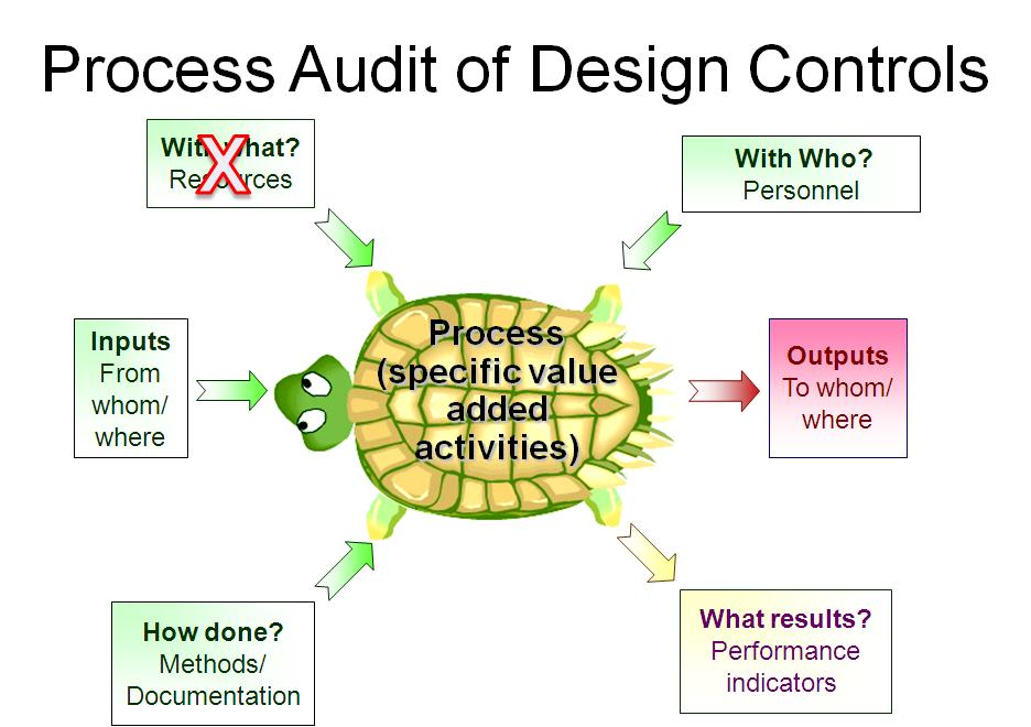
Auditing Design Controls – 7 Step Process

This blog reviews seven steps for effectively auditing design controls utilizing the ISO 13485 standard and process approach to auditing.

turtle diagram for design controls Auditing Design Controls   7 Step Process

Third-party auditors (i.e., – a Notified Body Auditor) don’t always practice what we preach. I know this may come as a huge shock to everyone, but sometimes we don’t use the process approach. Auditing design controls is a good example of my own failure to follow was it true and pure. Instead, I use NB-MED 2.5.1/rec 5 as a checklist, and I sample Technical Files to identify any weaknesses. The reason I do this is that I want to provide as much value to the auditing client as possible without falling behind in my audit schedule.

Often, I would sample a new Technical File for a new product family that had not been sampled by the Technical Reviewer yet. My reason for doing this is that I could often find elements that are missing from the Technical File before the Technical Reviewer saw the file. This gives the client an opportunity to fix the deficiency before submission and potentially shortens the approval process. Since NB-MED documents are guidance documents, I could not write the client up for a nonconformity, unless they were missing a required element of the M5 version of the MDD (93/42/EEC as modified by 2007/47/EC). This is skirting the edge of consulting for a third- party reviewer, but I found it was a 100% objective way to review Technical Files. I also found I could review an entire Technical File in about an hour.

What’s wrong with this approach to auditing design controls?

This approach only tells you if the elements of a Technical File are present, but it doesn’t evaluate the design process. Therefore, I supplemented my element approach with a process audit of the design change process by picking a few recent design changes that I felt were high-risk issues. During the process audit of the design change process, I sampled the review of risk management documentation, any associated process validation documentation, and the actual design change approval records. If I had time, I looked for the following types of changes: 1) vendor change, 2) specification change, and 3) process change. By doing this, I covered the following clauses in ISO 13485:2016: 7.4 (purchasing), 7.3.9 (design changes), 7.5.6 (process validation), 7.1 (risk management), and 4.2.5 (control of records).

So what is my bastardized process approach to auditing design controls missing? Clauses 7.3.1 through 7.3.10 of ISO 13485:2016 are missing. These clauses are the core of the design and development process. To address this, I would like to suggest the following process approach:

Step 1 – Define the Design Process

Identify the process owner and interview them. Do this in their office–not in the conference room. Get your answers for steps 2-7 directly from them. Ask lots of open-ended questions to prevent “yes/no” responses.

Step 2 – Process Inputs

Identify how design projects are initiated. Look for a record of a meeting where various design projects were vetted and approved for internal funding. These are inputs into the design process. There should be evidence of customer focus, and some examples of corrective actions taken based upon complaints or service trend analysis.

Step 3 – Process Outputs

Identify where Design History Files (DHF) are stored physically or electronically, and determine how the DHF is updated as the design projects progress.

Step 4 – What Resources

This is typically the step of a process audit where their auditor needs to identify “what resources” are used in the process. However, only companies that have software systems for design controls have resources dedicated to Design and Development. I have indicated this in the “Turtle Diagram” presented above.

Step 5 – With Whom, Auditing Training Records

Identify which people are assigned to the design team for a design project. Sometimes companies assign great teams. In this case, the auditor should focus on the team members that must review and approve design inputs (see Clause 7.3.2) and design outputs (see Clause 7.3.3). All of these team members should have training records for Design Control procedures and Risk Management procedures.

Step 6 – Auditing Design Controls Procedures and Forms

Identify the design control procedures and forms. Do not read and review these procedures. Auditors never have the time to do this. Instead, ask the process owner to identify specific procedures or clauses within procedures where clauses in the ISO Standard are addressed. If the process owner knows exactly where to find what you are looking for, they’re training was effective, or they may have written the procedure(s). If the process owner has trouble locating the clauses you are requesting, spend more time sampling training records.

Step 7 – Process Metrics

Ask the process owner to identify some metrics or quality objectives they are using to monitor and improve the design and development process. This is a struggle for many process owners–not just design. If any metrics are not performing up to expectations, there should be evidence of actions being taken to address this. If no metrics are being tracked by the process owner, you might review schedule compliance.

Many design projects are behind schedule, and therefore this is an important metric for most companies. Now that you have completed your “Turtle Diagram,” if you have more time to audit the design process, you can interview team members to review their role in the design process. You could also sample-specific Technical Files as I indicated above. If you are performing a thorough internal audit, I recommend doing both. To learn more about using the process approach to auditing, you can register for our webinar on the topic.

Auditing Design Controls – 7 Step Process Read More »

How to Write Design Control Procedures

The author has reviewed 100+ design control processes in his career, and this blog provides five steps to write design control procedures.

In my previous blog posting, I indicated six things that medical device companies can do to improve design controls. While the last posting focused on better design team leaders (WANTED: Design Team Needs Über-Leader), this posting focuses on writing stronger procedures. I shared some of my thoughts on how to write design control procedures just a few weeks ago, but my polls and LinkedIn Group discussions generated great feedback regarding how to write design control procedures.

No Need to Write Design Control Procedures

One of the people that responded to my poll commented that there was no option in the poll for “zero.” Design controls do not typically apply to contract manufacturers. These companies make what other companies design. Therefore, their Quality Manual will indicate that Clause 7.3 of the ISO 13485:2016 Standard is excluded. If this describes your company, sit back and enjoy the music.

1 Procedure Only

Another popular vote was “one.” If you only have one procedure for design controls, this meets the requirements. It might even be quite effective.

When I followed up with poll respondents, asking how many pages their procedures were, a few people suggested “one page.” These people are subscribing to the concept of using flow charts instead of text to define the design control process. I use the following diagram to describe the design process: The Waterfall Diagram!

waterfall diagram How to Write Design Control Procedures
From the US FDA Website.

I first saw this diagram in the first course I took on Design Controls. This is on the FDA website too. To make this diagram effective as a procedure, we might need to include some references, such as work instructions, forms, the US FDA guidance document for Design Controls, and Clause 7.3 of the ISO 13485:2016 Standard.

Many Design Control Procedures

The bulk of the remaining respondents indicated that their company has eight or more procedures related to design controls. If each of these procedures is short and specific to a single step in the Waterfall Diagram, this type of documentation structure works well. Unfortunately, many of these procedures are a bit longer.

If your company designs software, active implantable devices, or a variety of device types—it may be necessary to have more than one procedure just to address these more complex design challenges. If your company has eight lengthy procedures to design Class 1 devices that are all in the same device family, then the design process could lose some fat.

In a perfect world, everyone on the design team would be well-trained and experienced. Unfortunately, we all have to learn somehow. Therefore, to improve the effectiveness of the team, we write design control procedures for the team to follow. As an auditor and consultant, I have reviewed 100+ design control processes. One observation is that longer procedures are not followed consistently. Therefore, keep it short. Another observed is that well-designed forms help teams with compliance.

Therefore, if you want to re-write design control procedures, try the following steps:

  1. Use a flow chart or diagram to illustrate the overall process
  2. Keep work instructions and procedures short
  3. Spend more time revising and updating forms, instead of procedures
  4. Train the entire team on design controls and risk management
  5. Monitor and measure team effectiveness and implement corrective actions when needed

The following is a link to the guidance document on design controls from the US FDA website. In addition to the comments I made in this blog, please refer back to my earlier blog on how to write a procedure. You can also purchase Medical Device Academy’s design control procedure and forms.

How to Write Design Control Procedures Read More »

Design Team – Needs a Superwoman Leader

mona superwoman Design Team   Needs a Superwoman Leader
“Mona Superwoman” by Teddy Royannez (France)

This blog discusses the reasons for a female design team leader and the qualities and skills that she should possess to get maximum results out of her team.

Last November, Eucomed published a position paper titled, A new EU regulatory framework for medical devices: Six steps guaranteeing rapid access to safe medical technology while safeguarding innovation. While I have serious doubts that any government will ever be able to “guarantee” anything other than its own continued existence, I have an idea of how the industry can help.

The position paper identified six steps. Each of these steps has a comparable action that could be taken in every medical device company. My list of six steps is:

Only the best leaders have:

  1. Only one approach to design controls
  2. Stronger internal procedures
  3. Cross-pollination by independent reviewers
  4. Clear communication of project status to management
  5. Better project management skills

The most critical element to success is developing stronger design team leaders. Design teams are cross-functional teams that must comply with complex international regulations while simultaneously be creative and develop new products. This type of group is the most challenging type to manage. To be successful, design team leaders must be “Über-Leaders.”

Critical Design Team Leader Skills

The most critical skills are not technical skills but team leadership skills. The role of a design team leader is to ensure that everyone is contributing, without tromping on smaller personalities in the group. Unfortunately, there are more men in this role than women.

Why is this unfortunate? Because men have difficulty when it comes to listening (takes one to know one).

We need a leader that will be strong, but we also need someone that is in touch with the feelings of others and will use that skill to bring out the best of everyone on the team. This superwoman also needs to earn the respect of the male egos around the table. She needs to be an expert in ISO 14971, ISO 13485, Design Controls, Project Management, and managing meetings. Our beautiful heroine must also be a teacher because some of our team members will not know everything—even if they pretend to.

The Über-Leader will always remind the team that Safety & Efficacy are paramount. As team leaders, we must take the “high road” and do what’s right—even when it delays a project or fails to meet our boss’s unrealistic timetable. Superwoman must demand proof in the form of verification and validation data. It is never acceptable to go with an opinion.

She will remind us that compromise is the enemy, and we must be more creative to solve problems without taking shortcuts that jeopardize safety and efficacy. She will work harder on the project than anyone else on the team. She will keep us on schedule. She will whisper to get our attention, but she won’t be afraid to yell and kick our ass.

As Jim Croce says, “You don’t tug on Superman’s cape.” Superwoman is the only exception to this rule.


Design Team – Needs a Superwoman Leader Read More »

Design Input Requirements: 3 Common Errors

The author reviews three common errors related to design input requirements and uses examples to illustrate compliance.

I have been directly involved in dozens of design projects throughout my career, and during the past three years, I have audited 50+ Design Dossiers for CE Marking of Medical Devices. Throughout most of these design projects, I have noticed one common thread—a misunderstanding of design inputs.

ISO 13485 identifies design input requirements. These requirements are:

  1. Functional (7.3.2a)
  2. Performance (7.3.2a)
  3. Safety (7.3.2a)
  4. Statutory/Regulatory (7.3.2b)
  5. Previous and Similar Designs (7.3.2c)
  6. Essential Requirements (7.3.2d)
  7. Outputs of Risk Management (7.3.2e)
  8. Customer Requirements (7.2.1)
  9. Organizational Requirements (7.2.1)
Design Input Requirements: 3 Common Errors Reviewed

The most common error seems to be the failure to include the outputs of risk management. For those of you that have used design FMEA’s—that’s what the right-hand columns are for. When you identify suggested actions to mitigate risks with the current design, these actions should be translated into inputs for the “new and improved” model.

The second most common error seems to be a failure to consider regulatory requirements. There are two ways this mistake is frequently made: 1) Canadian MDR’s were not considered as design inputs for a device intended for Canadian medical device licensing, and 2) an applicable ISO Standard was not considered (i.e., – “State of the Art” is Essential Requirement 2 of the Medical Device Directive (MDD)).

The third most common error, and the one that drives me crazy, is a confusion of design outputs and design inputs. For example, an outer diameter of 2.3 +/- 0.05 mm is not a design input for a 7 French arterial catheter. This is a design output. The user need might be that the catheter must be small enough to fit inside the femoral artery and allow interventional radiologists to navigate to a specific location to administer therapy. Validation that the new design can do this is relatively straight forward to evaluate in a pre-clinical animal model or a clinical study. The question is, “What is the design input?”

Design Input Examples

Design inputs are supposed to be objective criteria for verification that the design outputs are adequate. One example of a design input is that the catheter outer diameter must be no larger than a previous design that is an 8 French catheter. Another possible design input is that the catheter outer diameter must be less than a competitor product. In both examples, a simple measurement of the OD is all that is required to complete the verification. This also gives a design team much more freedom to develop novel products than a narrow specification of 23 +/- 0.05 mm allows for.

If you are developing a Class II medical device for a 510(k) submission to the FDA, special controls guidance documents will include design inputs. If you are developing a Class IIa, Class IIb, or Class III medical device for CE marking, there is probably an ISO Standard that lists functional, performance, and safety requirements for the device. Regulatory guidance documents and ISO Standards usually reference test methods and indicate acceptance criteria. When you have a test method and acceptance criteria defined, it is easier to write a verification protocol. Therefore, design teams should always strive to document design inputs that reference a test method and acceptance criteria. If this is not done, verification protocols are much more difficult to write.

In my earlier example, the outer diameter of 2.3 +/- 0.05 mm is a specification. Unfortunately, many companies would document this as an input and use the final drawing as the output. By making this mistake, “verification” is simply to measure the outer diameter to verify that it matches the drawing. This adds no value, and if the specifications are incorrect, the design team will not know about it.,

A true verification would include a protocol that identifies the “worst-case scenario,” and verifies that this still meets the design input requirements. Therefore, if the drawing indicates a dimensional tolerance of 2.3 +/- 0.05, the “worst-case” is 2.35 mm. The verification process is to measure either a previous version of the product or a competitor’s catheter. The smallest previous version or competitor catheter tested must be larger than the upper limit of the design output for the outer diameter of the new catheter.

Design Input Requirements: 3 Common Errors Read More »

Scroll to Top