Today Americans remember Dr. Martin Luther King Jr, but this weekend I had the privilege to visit the Liberty Bell and saw the picture below.Today, the third Monday in January is the day Americans observe Dr. Martin Luther King Jr’s birthday. Dr. King was a leader of the Civil Rights Movement in the USA, but he also stood for peace. I like to think that on February 1, National Freedom Day, he would still be visiting our Liberty Bell in the City of Brotherly Love.
Saturday, I was in Philadelphia, and Tifany and I took the time to visit the Liberty Bell. It has been more than 30 years since I last visited the Liberty Bell in Philadelphia. The last time I was with my grandparents as a young boy. My grandfather was a Quaker, and he taught me every day about principles he believed in:
Peace
Religious Tolerance
Helping Others
He lived these principles in everything he did, and I remember most of his gentle greeting when he said hello to someone. If the other person said, “How are you today?” his reply would always be, “All the better for meeting you today.”
This was one of the Quakerisms he developed on his own over his life, and I encourage everyone reading this to do three things:
Use my grandfather’s greeting to make someone smile today.
Help someone else in need today.
Remember that peace was part of Dr. King’s message too.
The image above includes the following description: “In 1959, Dr. Martin Luther King Jr. and Dr. Emmanual Wright, leaders of the modern Civil Rights Movement, participated in the annual tradition of celebrating National Freedom Day, the commemoration of the Thirteenth Amendment, at the Liberty Bell begun by Dr. Wright’s father. Photograph. “Dr. Martin Luther King, Jr. and Dr. Emmanuel C. Wright at the Liberty Bell,” February 1, 1959. Courtesy, Urban Archives, Temple University Library.”
This blog summarizes the changes in FDA policy, released on April 27, 2020, as a new eCopy guidance for device manufacturers.
The date of the guidance above was updated, but the changes to the guidance do not represent any changes in policy. It is an update of contact information and a note regarding eCopies for EUA requests. In August 2016, I had a frustrating week where I had three (3) different submissions placed on eCopy hold by the FDA, three (3) separate times, for a total of nine (9) eCopy hold in the same week. That resulted in an extra $175 of FedEx charges and wasted six (6) USB flash drives. The biggest problem was the submission delay experienced by each client that week, which wasn’t very comfortable. This terrible, no good, dreadful week ultimately resulted in our company creating a new productized service–preparing FDA eCopies for clients and competitor consultants. We also became international experts on the FDA eCopy guidance. If my experience was this painful, there must be other people experiencing the same problem, or many people would experience this problem as soon as they tried to submit their next filing with the FDA.
For about 18 months, we helped many companies prepare FDA eCopy submissions, but then there was a government shutdown, and the FDA unofficially changed its policy. A printed paper copy of pre-submissions, 510ks, and De Novo classification requests would no longer be required. You only needed to print a paper copy of your cover letter and include an electronic copy on a CD, DVD, or USB flash drive. Despite this policy change, many clients still requested the printed copy because the FDA legislation was not yet changed, and there was no updated guidance. We explained to each client that the policy had changed, and only two clients asked us to print the paper copy anyway.
In October of 2018, the unofficial policy became official, but there was still no updated FDA eCopy guidance for us to share with clients. This situation frequency resulted in questions from clients about how they should phrase the “eCopy Statement” in their submission cover letter. The eCopy guidance that was current in 2018 stated that you should include the following phrase in your cover letter: “This submission includes an eCopy and a paper copy. The eCopy is an exact duplicate of the paper copy.” However, the paper copy consisted only of the cover letter, and the rest of the submission was solely provided in electronic format.
The FDA released a new pilot version of the eSubmitter software to help companies prepare 510(k) submissions and to streamline the FDA review of submissions in 2018. However, even electronic submissions prepared with eSubmitter must be sent by courier or mail to the FDA Document Center. In 2019, the FDA mentioned that they would be releasing new guidance documents regarding electronic submissions. Still, we were also told that the FDA has no near-term plans to enable companies to submit pre-submissions, 510ks, or De Novo classification requests to the FDA via an electronic submissions gateway (ESG).
Finally, on December 16, 2019, the FDA released a new eCopy guidance. The eCopy guidance was updated again on April 27, 2020, but the changes are updated to include emails, updated webpages, and a note regarding EUA requests.
July 2022 Update for the FDA eCopy process
The FDA created a Customer Collaboration Portal (CCP) for medical device manufacturers. Originally, the portal’s purpose was to provide a place where submitters can track the status of their submissions and verify the deadlines for each stage of the submission review process. Last week, on July 19, the FDA emailed all active FDA CPP account holders that they can upload both FDA eCopy and FDA eSTAR files to the portal 100% electronically. Since our consulting team sends out submissions daily, everyone on the team was able to test the new process. If you have a CCP account, you no longer need to ship submissions via FedEx to the Document Control Center (DCC).
What DID NOT change in the new eCopy guidance?
The file name requirements are identical. You can still organize your submission in volume structure or document-only structure. You are still limited to PDF file sizes of 50 MB. The eCopy will still be problematic for the FDA to upload if your submission exceeds 1 GB. You still need to ship your eCopy to the FDA Document Center unless you submit it to CBER instead of CDRH. You can and should continue to use the eCopy validation software module provided by the FDA to ensure that your eCopy will properly upload. The guidance barely changed in length; it’s just a few pages shorter now.
What DID change in the new eCopy guidance?
Only two things changed in the new guidance. First, there is no mention of an eCopy statement anywhere. Second, you must submit a cover letter in paper format (replaced by Zip file to FDA CCP), but it does not need to be included in the electronic format (that’s only recommended).
The “new” eCopy process is not any easier than the process we have used since February 2018. However, we did update our cover letter template. If you would like a copy, please register for our FDA eCopy webinar.
Should you create your own eCopies, or should you outsource?
If my job was Director of Regulatory Affairs (or a similar position), I would outsource. Regulatory managers in companies are swamped with trying to remain compliant with new and revised medical device regulations and changes to applicable standards.
Does it take one hour to create an eCopy?
No, we can prepare, validate, and upload an FDA eCopy in less than 15 minutes. This is only possible because we do this almost every day. On the last business day before the end of the FDA fiscal year (September 30), we average four (4) submissions on that day alone. We know exactly what to do, we know how to fix all of the most common errors, we know our validation software module is up-to-date, and we never run out of USB flash drives (replaced by Zip files to FDA CCP).
How long could it take you to create an eCopy?
If you haven’t done an eCopy in that past year, it could easily take you all day to create an eCopy. You have to read the new eCopy guidance document. You must format your submission according to the rules and proofread 100% of the folder and file names. You need to find a new flash drive. You need to save the submission on your USB flash drive. You need to run the eCopy validation software module.
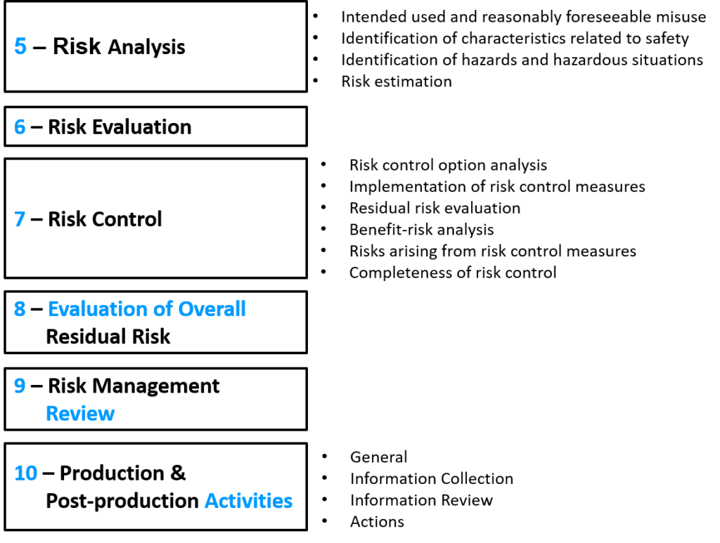
The 3rd edition of the risk management standard for medical devices, ISO 14971:2019, was released on December 16, 2019.
In October of 2018, I wrote a blog on the draft version of ISO 14971:2019 for risk management of medical devices. That article explained the differences between the different versions of the ISO 14971 standard (i.e., 2000, 2007, 2009, and 2012). I also explained what changed between ISO 14971:2007 and ISO/DIS 14971:2018. The final 2019 version of ISO 14971 3rd edition is now available.
The changes proposed in the draft included subtle changes to the names of the processes and a minor adjustment to the numbering of the clauses. Many of the annexes were also moved to ISO/TR 24971 guidance–which was released in 2020. The draft did not, however, result in a change in the overall process of risk management.
All of the changes that were discussed in my 2018 review were maintained in the final 2019 version that was released, but the ISO/TR 24971 guidance was not released at the same time as the committee had hoped for.
There are not any surprises in the 3rd edition (i.e., ISO 14971:2019). Therefore, I plan to wait until the ISO/TR 24971 guidance is released and then prepare a new blog specific to the guidance. If you are interested in training on the ISO 14971:2019 standard, the training I recorded on October 19, 2019, provides an excellent overview of these changes and highlights some of the challenges that you will encounter when trying to harmonize your risk management procedure between the ISO 14971:2019 standard and Regulation (EU) 2017/745.
This is a lot of information to absorb. Therefore, I recommend purchasing the October 2019 webinar and your copy of the ISO 14971 standard from AAMI. Anyone that has already purchased either the webinar or the procedure will receive an email offering them a discount on this new bundle that credits them for their previous purchase. If you have purchased both, you will receive credits for both purchases. Just think you can watch the video and read the new version of the standard while you are working out at the gym in January. Learn and burn!
This article explains the FDA regulations related to private labeled devices that are already 510k cleared and distributors want to import.
This article was initially inspired by a question asked on the Medical Devices Group website hosted by Joe Hage. Companies often ask about how to private labeled devices in the USA, because they are unable to find anywhere in the FDA regulations where private labeling of the device is described. The reason for this is because the FDA regulations for devices allow for the labeling to identify the distributor only—without any mention of the OEM manufacturer on the label. In contrast, most other countries have “own-brand labeling” regulations or regulations for private labeling devices. It is also important to remember that the FDA only approves devices through the pre-market approval (PMA) pathway. All other devices fall into one of three categories: 1) 510k exempt, 2) 510k cleared, or 3) De Novoclassification request approved. Devices that fall into the third category will subsequently fall into category 1 or 2 after the FDA approves the classification request.
Questions about the private labeled devices process for FDA
Our distribution company is interested in getting a private labeled devices agreement with an OEM to sell a Class II medical device in the USA. The OEM has 510(k) clearance, and the only product change will be the company’s name and address on the label. There will be no change to the indications for use. Please answer the following questions:
Is it legal to eliminate all mention of the OEM from the device labeling?
Who is responsible for complaint handling and medical device reporting? OEM or private-labeled distributor?
What is the process to get this private label for the Class II device?
How can our distribution company avoid paying the FDA user fee?
Answer to the first question about private labeled devices
The FDA is unique in that they allow either the distributor or the manufacturer to be identified on the label, but both are not required. Therefore, if Joe Hage were the distributor, and you were the manufacturer, there are two legal options for the private labeled device: 1) “Distributed by Joe Hage”, or 2) “Manufactured for Joe Hage.”
The manufacturer is not required to be identified on the label. However, the OEM must be registered and listed with the FDA. If the OEM is outside the USA, then the distributor must register and list with the FDA as the initial importer and reference the K number when they complete the FDA listing. There is no approval required by the FDA. You will need a quality agreement defining the roles and responsibilities of each party, but that is all.
Answer to the second question about private labeled devices
The quality agreement must specify which company is responsible for complaint handling (21 CFR 820.198) and medical device reporting (21 CFR 803). In this situation, the OEM is the specification developer, as defined by the FDA. Therefore, the OEM will be responsible for reporting and execution of recalls. Therefore, even if the distributor with a private label agreement is identified as the “complaint file establishment,” the OEM will still need to obtain copies of the complaint information from the distributor, and determine if medical device reporting and/or corrections and removals are required (i.e., recalls).
Answer to the third question about private labeled devices
There is no formal process for “getting a private label.” The entire private label process is negotiated between the distributor and the OEM with no involvement of the FDA. However, in the listing of devices within the FDA FURLS database, all brand names of the device must be identified. Therefore, the OEM will need to add the new brand name used by the distributor to their listing for the 510(k) cleared product. However, the FDA does have the option to keep this information confidential by merely checking a box in the device listing form.
Answer to the fourth question about private labeled devices
If the distribution company is the initial importer of a device into the USA, then the distributor must be registered with the US FDA as the initial importer, and the distributor will need to pay the FDA user fee for the establishment registration. That user fee is $5,236 for FY 2020, and there is no small business discount for this fee. The only way to avoid paying the user fee is to have another company import the device, who is already registered with the FDA, and to distribute the product for that company. I imagine some logistics brokers might be acting as an initial importer for multiple distributors to help them avoid paying the annual FDA user fee for establishments. That company might also be providing US Agent services for multiple OEMs. However, I have not found a company doing this.
Is private labeling of device legal in the USA?
The FDA is unique in that they allow either the distributor or the manufacturer to be identified on the label, but both are not required. Therefore, if Joe Hage were the distributor, and you were the manufacturer, there are two legal options for the private label: 1) “Distributed by Joe Hage”, or 2) “Manufactured for Joe Hage.”
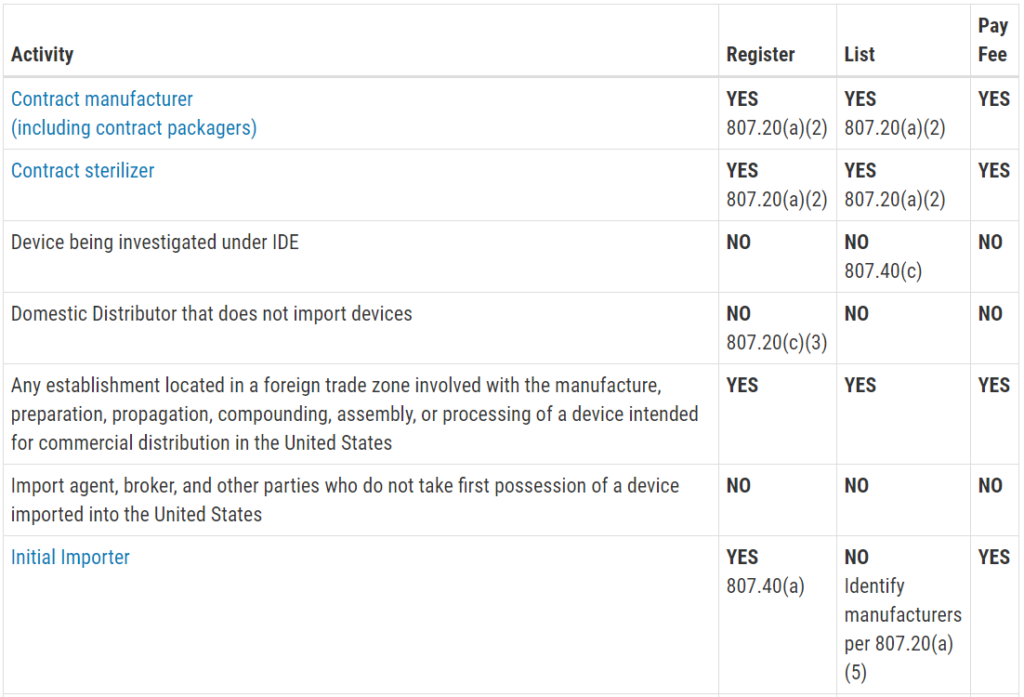
Who must register, list, and pay user fees for medical devices?
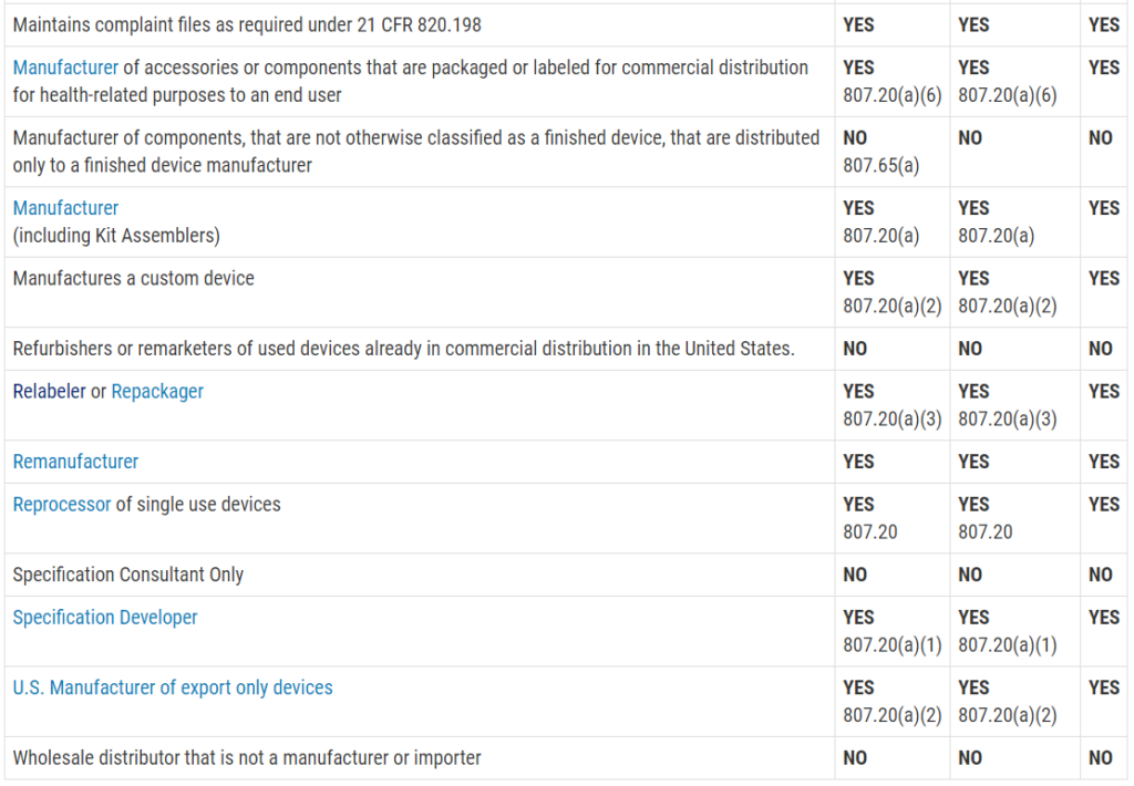
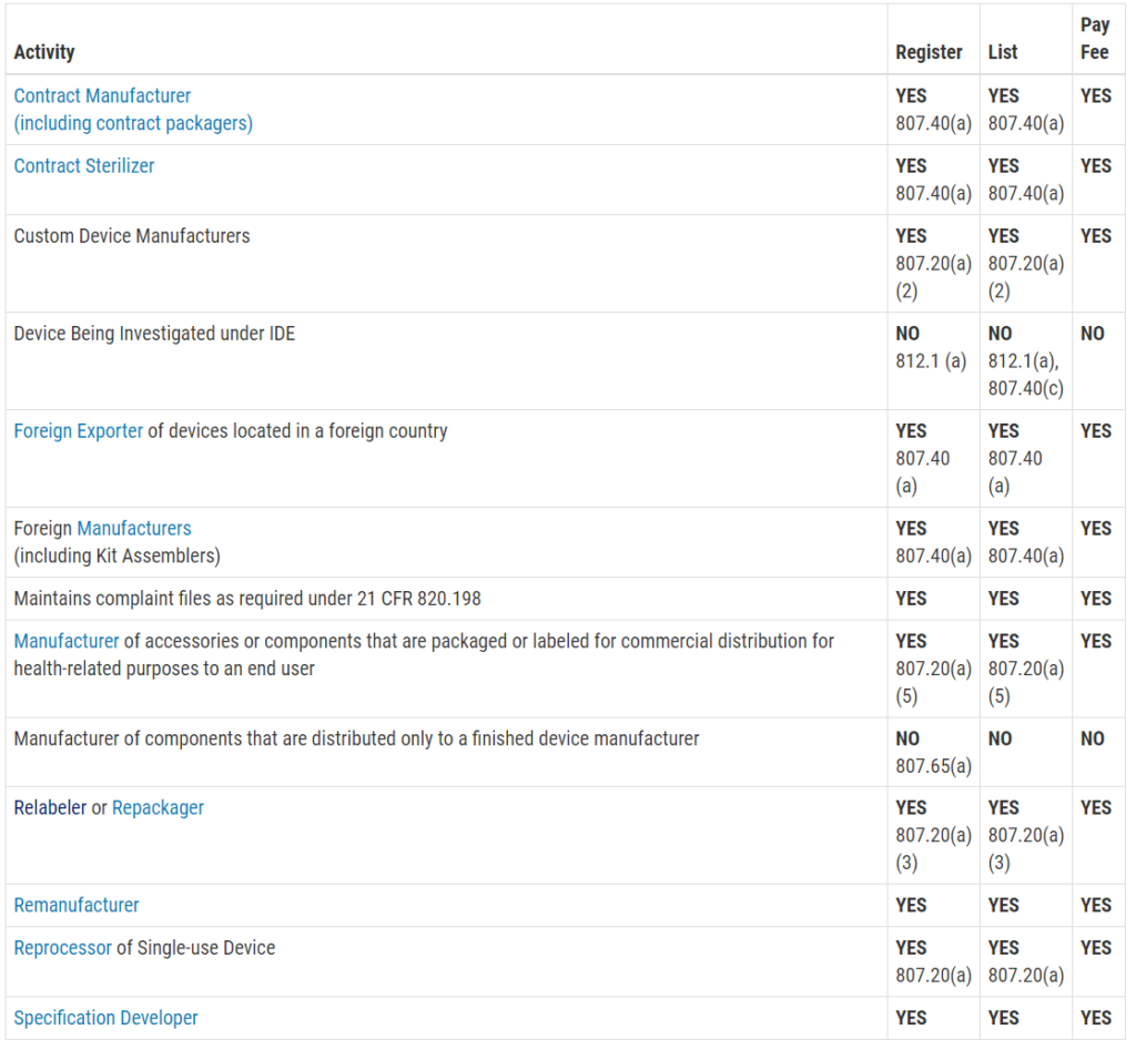
This question is frequently asked, and the table with the information was not visible on my mobile browser. Therefore, I copied the table from the FDA website and posted the information in the image below. The information is copied directly from the FDA website:
Registration and Listing Requirements for Domestic Establishments
Registration and Listing Requirements for Foreign Establishments
For products that are manufactured outside the USA, and imported into the USA, the initial importer is often the company identified on the label. There are two typical private labeling situations, but other possibilities exist:
If the initial importer owns the 510(k), then the manufacturer outside the USA is identified as the “contract manufacturer,” and the initial importer is identified as the “specifications developer.” Both companies must register their establishments with the FDA, and there needs to be a quality agreement between the two companies defining roles and responsibilities. The contract manufacturer outside the USA is not automatically exempt from reporting requirements and complaint handling. The contract manufacturer outside the USA may decide to label the product as a) “Manufactured by”, b) “Manufactured for”, or c) “Distributed by.” Options “a”, “b” and “c” would list the importer’s name because they own the 510(k), and they are the distributor. This situation often occurs when companies outside the USA want to sell a product in the USA, but they do not want to take on the responsibility of obtaining 510(k) clearance. These firms often believe this will exempt them from FDA inspections, but the FDA is increasingly conducting FDA inspections of contract manufacturers due to this private label situation.
If the manufacturer owns the 510(k), then the manufacturer outside the USA is identified as the “specifications developer” and the “manufacturer,” while the initial importer will be identified as the “initial importer.” The importer may also be specified as the complaint file establishment and/or repackager/relabeler in the FDA registration database. The manufacturer outside the USA will not be able to import the device into the USA without identifying an initial importer in the USA in the FDA FURLS database. The manufacturer outside the USA may decide to label the product as a) “Manufactured by”, b) “Manufactured for”, or c) “Distributed by.” Options “b” and “c” would list the importer’s name, while option “a” would list the manufacturer’s name. This situation often occurs when US companies want to be the distributor for a product made outside the USA, and the company wants a private labeled product. This also happens when the OEM wants the option to have multiple US distributors.
In both of the above private-label situations, the non-US firm must have a US Agent identified because the company is located outside the USA. The US Agent may be the initial importer, but this is not required. It could also be a consulting service that acts as your US Agent. The US Agent will be responsible for receiving communications from the FDA and confirming their role as US agents each year when the registration is renewed. Medical Device Academy offers this service to non-US clients we help obtain 510(k) clearance.
Follow-up questions
A Korean company, with a US distribution subsidiary, would like to private label a medical device with an existing 510(k) owned by another company in their name. Does the Korean company need a contract in place before private labeling? Does the US subsidiary and/or the Korean parent company need to be registered in the USA prior distribution of the private-labeled version of the device in the USA?
Rob’s response: Initially, it was unclear from the wording of the question as to whom is the 510(k) owner, which company will be on the label, who is doing the labeling, and who is doing the importing to the USA. The person asking Joe Hage this question tried clarifying their question via email, but we quickly switched to scheduling a phone call using my calendly link. I have reworded the question above, but here are some of the important details I learned during our phone call:
The person asking was already acting as the relabeler, repackager, and they were distributing the product in the USA. This person’s company is also registered with the FDA.
The device is 510(k) cleared by another US company, and there is no need to worry about the complications of an initial importer being identified for a product manufactured in the USA.
In this situation, the relabeler/repackager can relabel the product for the Korean company’s US subsidiary as long as there is a quality agreement in place for all three parties (i.e., relabeler, distributor, and manufacturer). There is no need for the Korean parent company to register with the FDA. There is no need for a new 510(k) submission, and the US subsidiary does not need to register with the FDA—as long as the quality agreement specifies that the US subsidiary will maintain records of distribution, facilitate recalls if required, and notify the manufacturer of any potential complaints and/or adverse events immediately. The manufacturer with 510(k) clearance will be responsible for complaint handling, medical device reporting, and execution of recalls according to the agreement. The relabeler will be responsible for maintaining records of each lot of product that is relabeled for the US subsidiary, and the relabeler must maintain distribution records that link the original manufacturer’s lot to the lot marked on the relabeled product.
If you have questions about the private labeling of your device, please contact us.
This article explains how you should be integrating usability testing into your design control process–especially formative usability testing.
Why you should be integrating usability testing into the design
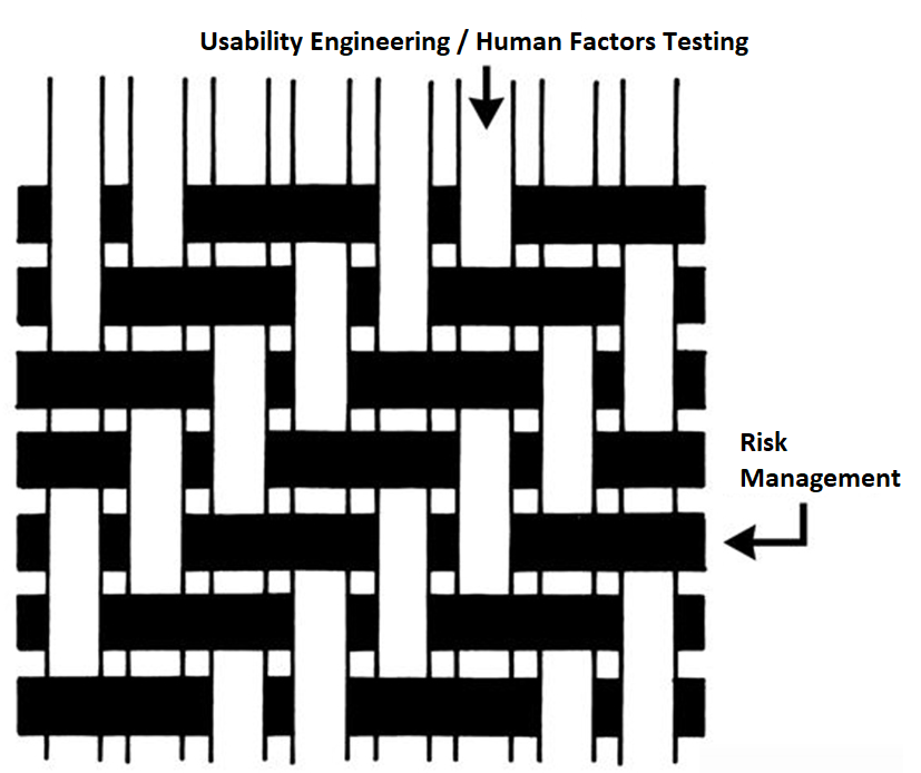
We recently recorded an updated usability webinar and released a usability procedure (SYS-048) with help from Research Collective–a firm specializing in human factors testing. After listening carefully to the webinar, and reading through the new usability procedure, I felt we needed to update our combined design/risk management plan to specify formative testing during phase 3 and summative (validation) testing during phase 4 of the design process. This is necessary to ensure your usability testing is interwoven with your risk management process. Integrating usability testing into all phases of your design process is critical–especially design planning (phase 1), feasibility (phase 2), and development (phase 3).
Integrating usability testing into your design plan helps identify issues earlier
During the usability training webinar, Research Collective provided a diagram showing the various steps in the usability engineering process. The first five steps should be included in Phases 1 and 2 of your design process. Phase 1 of the design process is planning. In that phase, you should identify all of the usability engineering tasks that need to be performed during the design process and estimate when each activity will be performed. The first of these usability activities is the identification of usability factors related to your device. Identifying usability factors is performed during Phase 2 of your design process before hazard identification.
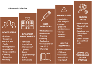
Before performing hazard identification, which should include identifying potential use errors, you need to identify five key usability elements associated with your device:
prospective device users during all stages of use must be defined
use environments must be identified
user interfaces must be identified
known use errors with similar devices and previous generations of your device must be researched
critical tasks must be described in detail and analyzed for potential use errors
Defining users must include the following characteristics: physical condition, education, literacy, dexterity, experience, etc. Use environment considerations may consist of low lighting, extreme temperatures or humidity, or excessive uncontrolled motion (e.g., ambulatory devices). User interfaces may include keyboards, knobs, buttons, switches, remote controllers, or even a touch screen display.
Often the best reason for developing a new device is to address an everyday use error that is inherent to the design of your current device model or a competitor’s product. Therefore, a thorough review of adverse event databases and literature searches for potential use errors is an important task to perform before hazard identification. This review of adverse event data and literature searches of clinical literature are key elements of performing post-market surveillance, and now ISO 13485:2016 requires that post-market surveillance shall be an input to your design process.
Finally, the step-by-step process of using your device should be analyzed carefully to identify each critical user task. User tasks are defined as “critical” for “a user task which, if performed incorrectly or not performed at all, would or could cause serious harm to the patient or user, where harm is defined to include compromised medical care.” Not every task is critical, all critical tasks must be identified, and ultimately you need to verify that each critical task is performed correctly during your summative (validation) usability testing.
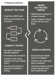
Evaluating Risk Control Options – Formative Usability Testing in Phase 3 (Development)
Once your design team has conducted hazard identification and identified your design inputs (i.e., design phase 2), you will begin to evaluate risks and compare various risk control options. Risk control option analysis requires testing multiple prototype versions to assess which design has the optimum benefit/risk ratio. This is an iterative process that involves screening tests. For any use risks you identify, formative usability testing should be performed. Sometimes the risk controls you implement will create new use errors or new risks of other types. In this case, you must compare the risks before implementing a risk control with risks created by the risk control.
Ideally, each design iteration will reduce the risks further until all risks have been eliminated. The international risk management standard (ISO 14971) states that risks shall be reduced as low as reasonably practicable (ALARP). However, the European medical devices regulations require risks to be reduced as far as possible, considering the state-of-the-art. For example, all small-bore connectors in the USA are now required to have unique connectors that are incompatible with IV tubing Luer lock connections to prevent potential use errors. That requirement is considered “state-of-the-art.” If your device is marketed in both the USA and Europe, you will need to reduce errors as far as possible–before writing warnings and precautions in your instructions for use.
Reaching the point where use errors cannot be reduced any further may require many design iterations, and each iteration should be subsequently evaluated with formative usability testing. Formative testing can be performed with prototypes, rather than production equivalents, but the formative testing conditions should also address factors such as the use environment and users with different levels of education and/or experience. Ultimately, if the formative testing is done well, summative (validation) testing will be a formality.
Risk Control Effectiveness During Phase 4 – Summative Usability Testing during Verification
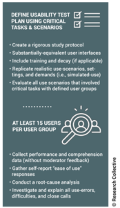
Once your team freezes the design, you will need to conduct verification testing. This includes integrating usability testing into the verification testing process. Summative (validation) testing must be performed once your design is “frozen.” If you are developing an electrical medical device, then you will need to provide evidence of usability testing as part of your documentation for submission to an electrical safety testing lab for IEC 60601-1 testing. There is a collateral standard for usability (i.e., IEC 60601-1-6). For software as a medical device (SaMD), you will also be expected to conduct usability testing to demonstrate that the user interface does not create any user errors.
When you conduct summative (validation) testing, it is critical to make sure that you are using samples that are production equivalents rather than prototypes. Also, it is crucial to have your instructions for use (IFU) finalized. Any residual risks for use errors should be identified in the precautions section of your IFU, and the use of video is encouraged as a training aid to ensure use errors are identified, and the user understands any potential harm. When the summative testing is performed, there should be no deviations and no use errors. Inadequate identification of usability factors during Phase 2, or inadequate formative testing during Phase 3, is usually the root cause of failed summative testing. If your team prepared sufficiently in Phase 2 and 3, the Phase 4 results would be unsurprisingly successful.
Additional Training Resources for Usability Engineering
The following additional training resources for usability engineering may be helpful to you:
This article explains what a pFMEA is (i.e. Process Failure Modes and Effects Analysis) and how to use them as part of your risk management process.
I recently had someone ask for help understanding the Process Failure Mode and Effect Analysis (pFMEA) a little better. I can’t blame them, because I was lost the first time I tried to fill out a form for one. It can be confusing and overwhelming if you have never created one before.
First things first, what is a pFMEA
FMEA= Failure Modes and Effects Analysis
A lower-case letter will come before the FMEA, and that denotes the ‘what’, of what the failure is that is being analyzed. A pFMEA will often be examining process failures where a dFMEA might evaluate design failures.
Some systems capitalize all the letters. Some capitalize none. That is not what is important as long as it is consistent throughout your system. Everyone should be able to easily understand that whatever variation of pfmea is used; it means “process failure modes and effects analysis.”
What does a pFMEA do?
A pFMEA will break down your manufacturing process into its individual steps and methodically examine them for potential risks or failures. For companies that utilize ourTurn-Key Quality Management System, FRM-025 process Failure Modes, and Effects Analysis can be used as a template.
For this example, we will look at receiving inspection of injection-molded casing parts for a medical device. This receiving inspection includes a manual inspection of 10 randomly selected parts out of each delivery of 100 using an optical overlay.
Process Step
This area, as the section title suggests, is the process step. When looking at the process as a whole, the pFMEA will break it down into each and every step included in that process. This area is simply that individual step that is going to be examined.
The Process Step or item function depending on what your form uses for this scenario, is going to be part of the random sampling for manual inspection of the received parts using an optical overlay. Our example is going to be the backlighting element of the optical overlay display. The backlighting element will illuminate the inspected part against the template to verify that the part is within specific dimension criteria.
Potential Failure Modes
A failure mode is a way in which that process step might fail. Since it is failure modeS, it needs to be considered that there may be more than one way for the process step to fail. Do not be fooled that because this box on the form has been filled in that the pFMEA will be complete. A thorough examination of all of the possible failures should be investigated.
Our example in this process requires the backlighting element to illuminate a visual template over the parts. The light not illuminating properly is a potential failure mode of this process.
Potential Effects of Failure
the potential effects of the failure is a look into what the ramifications would be if that failure for that process step actually happened.
In our scenario, one of the potential effects of the lighting not functioning properly is that parts outside of the designated sizing acceptance criteria may be accepted rather than rejected as non-conforming parts.
S (Severity)
The next area is the first area that requires an estimated grading of the failure. That is ‘Severity’ which is abbreviated as S. There is a scale provided in the rating section of FRM-025 that outlines the numbering system that Medical Device Academy uses.
In this case, our example is using molded plastic pieces of the outside casing of a medical device. Pieces that are too large or too small will not fit when making the final assembly of the device. These plastic pieces do not happen to be patient contacting, and do not affect the function of the device.
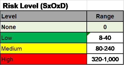
The evaluation of this failure is determined to have no potential effect on patient safety or increase any potential for risk of harm, therefore the severity is assigned as a ‘business risk’ meaning that it bears no risk for the user or the patient. This makes the Severity Score 0.
Causes of Failure
This column is exactly that. What might cause this identified failure to happen? In our example might be the light bulbs in the overlay machine may slowly burn out over time with use. This burnout causes potential failure.
If the bulb is expected to only have a lifetime of 100 hours, then the more hours the bulb is used, the dimmer the light may become. A slowly dimming light decreases the sharpness of the overlay template and our parts that are supposed to have a + or – size criteria of 10% now have a fuzzy template that in reality changes the overlay to show closer to + or – 13%. Now parts that are too small or too large may be accepted.
O (Occurrence/Probability)
This grading criterion is also found in the Rating section of FRM-025. This is how often the failure is expected to occur. How often will the lighting element of our optical overlay fail to function in the appropriate manner for this cause?
Hopefully not very often. In fact, regularly scheduled maintenance and calibration of the overlay machine could prevent this from ever happening in the best-case scenario. Our evaluations determine that the probability of this happening is low. However, since we cannot be certain it will never happen the potential for this risk exists and makes the Occurrence score a 4.
Current Process Controls
What is currently being done to control this risk? Our example uses regularly scheduled maintenance and calibration to prevent bulb burnout affecting the overlay.
D (Detectability)
Our current process is based on routine maintenance and visual inspection. This means that the bulb burnout is something that is visually inspected for and visual inspections for detectability on the rating scale are graded as 8. This chart is found in the Rating Section of FRM-025.
RPN (Risk Priority Number)
This is a number that is found by multiplying the Severity, by the Probability, by the Detectability. In our example, the numbers RPN is 0X4X8=32 for an RPN of 32 which is considered LOW.
pFMEA math
Below is a short video explaining the math behind calculating the Risk Priority Number
Recommended Actions
What if anything can be done to improve this process? In our example, a recommended action may be to transfer from visual only inspections to verification of light output by the meter. This makes the Detectability of the failure measurable by meter or gage which is a detectability score of 4.
This changes the RPN now to 0X4X4=16
The pFMEA shouldn’t be a solo thing
If it can be avoided this type of analysis should be done by a multidisciplinary team. Sometimes in smaller companies, people end up having to wear more than one hat. There are many entrepreneurs that have to function as the CEO/CFO/Design Engineer/RA/QA manager.
Ideally, a team approach should be used if feasible. Have the management level staff who have ownership of the processes participating in this analysis. They should know the process more intimately than anyone else in the company and should have more insight into the possible failure modes of the processes as they have likely seen them first hand. They are also the type of employee who would know the types of recommended actions to control the risk of those failures as well.
The pFMEA should also be a living document
As new failure modes are discovered they should be added to your pFMEA. A new failure mode might be discovered through a CAPA because the process had an actual failure that was not originally analyzed. Take an instance like that as an opportunity for improvement and to update your pFMEA as part of a living breathing risk management system. Also, use this as a time to re-brainstorm potentially similar failure modes that may not have been considered previously so that they can be controlled before they happen.
If you took the time to watch the video above it is also mentioned that in some instances the very first FMEA must be based on estimates because there is no data. Managers and engineers may be forced to estimate the probability of occurrence. If that is the case the FMEA should be updated in the future to adjust the (O) score to reflect what is occurring in actuality based on real data and not the theoretical data that was used for the initial estimate.
On August 9, 2019, three generations of my family left Glastonbury, CT, on a two-week hiking expedition to complete three of the highest peaks in the USA.
Our plan for the hiking expedition was to hike four of the highest peaks. My father, Bob Packard (age 77), is trying to complete all 50 of the highest peaks in each of the United States. For this trip we planned to hike the following mountains:
Wheeler Peak – New Mexico
Kings Peak – Utah
Borah Peak – Idaho
Granite Peak – Montana
Bailey Packard (18), Noah Packard (20), Rob Packard (47), and Bob Packard (77) started on Friday, August 9, from Glastonbury, CT.
Then we drove West for a long time. On Saturday, August 10, we stopped at the Waffle House.
Then we got back in the car.
Finally, on Sunday, August 11, we arrived at the base of Wheeler Peak. We decided to hike it that day despite not acclimating to the altitude and not sleeping in two days.
Then we headed back across the ridge and down to the car. The evening we drove to Colorado and slept. The following morning, Monday, August 12, we drove through Colorado.
That evening we arrived at Henry’s Fork Trail Head in Utah several hours after dark. We pitched tents in the parking area and slept for the night. In the morning, Tuesday, August 13, we woke to ice on our tents. Then we began the long hike into the valley (see Bailey’s video above).
We were all carrying too much gear, and we needed some rest.
While we enjoyed the view of the valley.
Later we saw a couple of moose (Bailey got close enough for a selfie).
We slept the night just below Gun Sight Pass and then headed up Kings Peak in the morning of Wednesday, August 14.
Another spectacular view.
Then we headed back across the ridge (very challenging and exposed).
That afternoon Bailey got lost, but we found him back at the tents several hours later just before dark. Noah was exhausted and took a nap in the middle of the Gun Sight Pass. We all slept well and hiked back to the car in the morning of Thursday, August 15.
Then we drove to Idaho Falls, and we had all you can eat steak at Stockman’s.
We took at rest day on Friday, August 16. On Saturday, it was perfect weather, and we drove to Borah Peak in Idaho–just two hours Northwest from Idaho Falls. We arrived just after 6 am and began hiking as the sun rose.
Now I understand why Wheeler was rated a 1+ in difficulty. Kings Peak was rated a 2+ in difficulty, and Borah is 3+ in difficulty. There is a 2,000+ foot cliff on both sides of a goat path across a knife-edge. There is sharp, jagged shale everywhere and no trees. Winds are fierce, and it’s not a windy day. Temperatures were in the low 40s. I decided to “chicken out” just before we got to “Chicken Out Ridge.”
The ice bridge was not expected, and dozens of weekend hikers with no experience were trying to crawl across the ice. Bailey used his knife for extra grip on the ice. Bob was almost knocked off the mountain by a falling boulder, and they made it to the peak waiting for Bailey’s pictures to be added later.
Then we all headed down the mountain.
The following day, Sunday, August 18, we drove home our feet were too sore to attempt Granite Peak. But along the way, we stopped on Monday, August 19 at Portillo’s for
Thank you for your support, and thank you to Noah and Bailey for joining my dad and me on this hiking expedition. These are memories we’ll never forget.
This article describes what a gap analysis is in the context of managing your quality system when standards and regulations are updated.
What is a Gap Analysis? An introductory look.
Well, that depends on the context. The dictionary definition is “A technique that businesses use to determine what steps need to be taken in order to move from its current state to its desired, future state. Also called need-gap analysis, needs analysis, and needs assessment.”
For the most part, this is correct, but we need to tweak it just a little bit to fit better into our regulatory affairs niche, specifically medical device manufacturers. A gap analysis for financial investment or an advertising firm will be very different than one for a medical device distributor. It might even be better served to be called a compliance assessment/gap analysis, but I am sure someone else has thought of that long before me.
For our purposes, the gap analysis is a formal comparative review of an internal process or procedure against a standard, good practice, law, regulation, etc. This blog article will be an introductory look into that process. We also created a procedure case study that shows how a gap analysis can be used to review your management procedure against the requirements in ISO 13485:2016.
What are the two BIG goals of a Gap Analysis?
It sounds like a simple exercise, but the gap analysis or “GA” for short can have two very different but complementary functions. Rather than simply hunting for areas of non-compliance, the first goal is to find and demonstrate areas of compliance.
The second more obvious goal is to find the gaps between the process and the regulatory requirements they are being compared against.
Why is demonstrating compliance important?
Because this is a formal documented review, a gap analysis provides documentation in a traceable manner of meeting the requirements that have been laid out. That traceability is important because it allows anyone to read the report, see the requirement, and locate the area of the procedure that demonstrates conformity with that requirement.
The report itself is an objective tool, not something that is meant to be a witch hunt. The gap analysis will compare document contents. If you want to verify that the entire process is fully compliant, you will need to dig deeper and observe if the activities laid out within the procedure are being performed per the procedure instructions. It is possible to draft procedures that are compliant with text requirements but non-compliant in the manner that the actions are being performed and documented.
What about gaps?
The gaps, or areas of non-compliance highlight opportunities for improvement, if there are any. A gap assessment may not find any gaps and present a report that clearly and neatly outlines and explains how each regulatory requirement is being met.
If there are any gaps identified, that does not mean that there is cause for concern. This should be viewed instead as an opportunity for improvement. Standards and procedures change over time, and, naturally, procedures and processes will have to change with them.
The very act of the gap analysis shows that there is a documented effort towards continual improvement as long as the gaps are addressed.
Addressing the Gaps
The report is ideally the first and last step, and you have a wonderful piece of paper to show that someone checked, and all of the required areas are being met. However, this is not always the case. When there are gaps, they must be filled.
Addressing a gap should happen in a traceable manner, one that shows it was identified, acknowledged, and then how it was fixed. Something that might be addressed through your CAPA process, but that is a topic for a different time.
In Closing
The compliance assessment/gap analysis is a singular tool used in the overall maintenance of a quality system. Its actions and performance are similar to a simplified type of audit, but the gap analysis itself is not going to replace your regularly scheduled audit activities. However, it will help you monitor and keep your fingers on the overall pulse of your quality system. This is also especially helpful in situations where standards and regulations are updated, and your quality system needs to be evaluated and updated accordingly.
For more in-depth education in specialized areas of the assessment, look into our training on Technical File Auditing for MDR compliance against Regulation (EU) 2017/745 at the link below.
This article explains what to look at and what to look for when you are auditing technical files to the new Regulation (EU) 2017/745 for medical devices.
Your cart is empty
On August 8th, 2019, we recorded a live webinar teaching you what to look at and what to look for when you are auditing technical files (a link for purchasing the webinar is at the end of this article). Technical files are the technical documentation required for CE Marking of medical devices. Most quality system auditors are trained on how to audit to ISO 13485:2016 (or an earlier version of that standard), but very few quality system auditors have the training necessary to audit technical files.
Why you’re not qualified to auditing technical files
If you are a lead auditor, you are probably a quality manager or a quality engineer. You have experience performing verification testing and validation testing, but you have not prepared a complete technical file yourself. You certainly can’t describe yourself as a regulatory expert. You are a quality system expert. A couple of webinars on the new European regulations are not enough to feel confident about exactly what the content and format of a technical file for CE marking should be.
Creating an auditing checklist
Most auditors attempt to prepare for auditing the new EU medical device regulations by creating a checklist. The auditor copies each section of the regulation into the left column of a table. Then the auditor plans to fill in the right-hand columns of the table (i.e., the audit checklist), with the records they looked at and what they looked for in the records. Unfortunately, if you have never created an Essential Requirements Checklist (ERC) before, you can only write in your audit notes that the checklist was completed and what the revision date is. How would you know if the ERC was correctly completed?
In addition to the ERC, now called the Essential Performance and Safety Requirements (i.e., Annex I of new EU regulations), you also need to audit all the Technical Documentation requirements (i.e., Annex II), all the Technical Documentation on Post-Market Surveillance (i.e., Annex III), and the Declaration of Conformity (i.e., Annex IV). These four annexes are 19 pages long. If you try to copy and paste each section into an audit checklist, you will have a 25-page checklist with more than 400 things to check. The result will be a bunch of checkboxes marked “Yes,” and your audit will add no value.
Audits are just samples
Every auditor is trained that audits are just samples. You can’t review 100% of the records during an audit. You can only sample the records as a “spot check.” The average technical file is more than 1,000 pages long, and most medical device manufacturers have multiple technical files. A small company might have four technical files. A medium-sized company might have 20 technical files, and a large device company might have over 100 files. (…and you thought the 177-page regulation was long.)
Instead of checking many boxes, “Yes,” you should look for specific things in your audit records. You also need a plan for what records to audit. Your plan should focus on the essential records and any problem areas identified during previous audits. You should always start with a list of the previous problem areas because there should be corrective actions that were implemented, and the effectiveness of corrective actions needs to be verified.
Which records are most valuable when auditing technical files?
I recommend selecting 5-7 records to sample. My choices would be: 1) the ERC checklist, 2) the Declaration of Conformity, 3) labeling, 4) the risk management file, 5) the clinical evaluation report, and 6) post-market surveillance reports, and 7) design verification and validation testing for the most recent design changes. You could argue that my choices are arbitrary, but an auditor can always ask the person they are planning to audit if these records would be the records that the company is most concerned about. If the person has other suggestions, you can change which records your sample. However, you don’t want to sample the same records every year. Try mixing it up each year by dropping the records that looked great the previous year, and adding a few new records to your list this year.
What to look for when auditing technical files
The first thing to look for when you audit records: has the record been updated as required? Some records have a required frequency for updating, while other records only need to be updated when there is a change. If the record is more than three years old, it is probably outdated. For clinical evaluation reports and post-market surveillance reports, the new EU regulations require updating these reports annually for implantable devices. For lower-risk devices, these reports should be updated every other year or once every three years at a minimum.
Design verification and design validation report typically only require revisions when a design change is made, but a device seldom goes three years without a single change–especially devices containing software. However, any EO sterilized product requires re-validation of the EO sterilization process at least once every two years. You also need to consider any process changes, supplier changes, labeling changes, and changes to any applicable harmonized standards.
Finally, if there have been any complaints or adverse events, then the risk management file probably required updates to reflect new information related to the risk analysis.
Which record should you audit first?
The ERC, or Essential Performance and Safety Requirements checklist, is the record you should audit first. First, you should verify that the checklist is organized for the most current regulations. If the general requirements end with section 6a, then the checklist has not been updated from the MDD to the new regulations–which contains nine sections in the general requirements. Second, you should make sure that the harmonized standards listed are the most current versions of standards. Third, you should ensure that the most current verification and validation reports are listed–rather than an obsolete reports.
More auditor training on technical files…
We recorded a live webinar intended to teach internal auditors and consultants how to perform a thorough audit of CE Marking Technical Files against the requirements of the new European regulations–Regulation (EU) 2017/745.
With access to this training webinar, we are also providing a native presentation slide deck, and an audit report template, including checklist items for each of the requirements in Annex I, II, III, and IV of the MDR.
We also provide an exam (i.e., a 10-question quiz) to verify training effectiveness for internal auditors performing technical file auditing. If you submit the completed exam to us by email in the native MS Word format, we will correct the exam and email you a training certificate with your corrected exam. If you have more than one person that requires a training certificate, we charge $49/exam graded–invoiced upon completion of grading.
Technical File Auditing for Compliance with MDR
This webinar provides an audit report template and teaches auditors how to conduct technical file auditing for compliance with Regulation (EU) 2017/745.
Price: $129.00
In addition to this webinar on auditing technical files, other training webinars are available. For example, we have a webinar on risk management training. If your firm is preparing for compliance with the new MDR, you might also be interested in the following information provided on this website:
A CE Marking procedure including templates for the Essential Requirements, a Declaration of Conformity, and a Technical File Index.
A blog outlining how to create your Quality Plan for compliance with the MDR
An 8-part webinar-based course reviewing the requirements of Regulation (EU) 2017/745 and comparing the requirements with the MDD (93/42/EEC as modified by 2007/47/EC).
Please note: A link for logging into this Zoom webinar will be delivered to the email address provided in the shopping cart transaction. After verifying the transaction, please check your email for the login information. To view the available webinars, click here. If you cannot participate in the live Zoom webinar, a link for downloading the recording will be emailed to you.
This article identifies one overlooked secret to accelerating design projects that you can implement immediately, and it will work on every project.
You would love to cut a few weeks off the launch schedule for your device. If you had a magic wand, what would you wish for? The trick to accelerating design projects is not an unlimited budget, hiring ten more engineers, or paying a Nationally Recognized Testing Laboratory (NRTL) to only work for you.
I know a secret for accelerating design projects that will work, but first, you need to understand why projects take as long as they do. Yes, I worked on a few design teams, but I learned the most from watching companies make mistakes that created delays and cost them time. Sterility tests can not be made shorter, guinea pig maximization tests (GPMT) can’t be completed in four weeks, and your electrical safety testing report will not be delivered when the lab promised it would be.
Accelerating design projects by preventing testing delays
The primary source of delay is not that testing is delayed, but rather the testing is not started as early as it could be. Some managers believe that the solution is to use a Gantt chart. Unfortunately, Gantt charts are not a solution. Gantt charts are just tools for monitoring projects. There is much more to project management. If you forget to do just one test, your entire project will be delayed until that test is finished. Therefore, making sure you identify every required test is an essential early project task–even before you start designing your device. You also need to update the plan when things change.
Start with a generic template for your testing plan
Our firm has a template for a device testing plan that we use for every pre-submission request. Getting help in creating your testing plan is one of the most important reasons to hire our firm to help you with a pre-submission request. Surprisingly, our template is more comprehensive than most design plans. What makes our plan surprising is that it’s a generic testing plan that I created in 30 minutes. If you would like it, just email me at rob@13485cert.com. We also have an updated template for combined design and risk management plans.
I’m not suggesting that our plan template already includes every single safety and performance test. Our testing plan does not include everything. However, we spend several hours looking for applicable guidance documents and researching the testing requirements for your device. Then we add the requirements we find to your customized testing plan in the pre-submission request.
Basics of shortening the critical path
If your testing plan includes 100% of the safety and performance tests that you need, your project will still be unnecessarily delayed. The reason for the unnecessary delay is that you are not taking advantage of the three most important timing factors:
First, do every test in parallel that you can.
Second, identify any tests that must be done sequentially.
Third, protect your critical path from further delays.
If the three “tricks” I listed above are new to you, you might consider reading more about a single-minute exchange of die (SMED) techniques, and applying the theory of constraints to project management:
In summary, I gave you several clues to the one secret. But the one secret is simple and practical. You need someone on your team who only focuses on the testing plan. Usually, every person on a design team is multitasking, but none of us can focus when we are multitasking. As the design project manager, it would be impossible for you to focus on one task. You are a project manager of a design team, and managing a project team is inherently all about multitasking. Therefore, you need to give one person on your team the task of focusing on the testing plan throughout the entire project. It doesn’t have to be the same person during every phase of the project. In fact, by rotating who that person is, each person assigned this responsibility only needs to be dedicated for a short duration. This is a critical concept. One person must be focused on your testing plan, and that person must be dedicated to that task as long as they are responsible for focusing on your testing plan. You might even consider making a big deal out of it…
Managers are always looking for creative ways to motivate teams. Custom t-shirts are fun, you can quickly design a different t-shirt for each role on the team, everyone can wear their t-shirt to team meetings, and the testing plan t-shirt will identify who has the responsibility for focusing on the secret to completing the project on schedule. You can order one of these t-shirts from us for $15. I dare you to compare the cost of a few custom t-shirts with the other solutions you were considering.
Our Testing Plan is my life T-Shirt
Please click the button to confirm that you'd like to receive the t-shirt shown in the picture. Please let us know what size you would like (M, L, XL, 2XL, 3XL). Only white t-shirts available with black graphics. We also need your shipping address. Shipping via US Postal Service is FREE. If you want the t-shirt expedited, we can ship it via FedEx to you. We will invoice you for the cost of our FedEx shipping to your location.
Price: $15.00
Your cart is empty
If you liked this article, please share it. If you are interested in design control or risk management training, consider purchasing one of our webinars on those topics for your company.